background image

User Manual  


46 


i Series / iX Series 

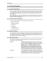
4.2.4  PROGRAM Menu 


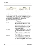
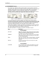
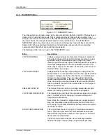
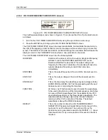
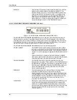
Figure 4-8:  PROGRAM Menu 

The PROGRAM menu is shown in Figure 4-8. It can be reached in one of two ways: 

1.  by selecting the PROGRAM entry in the MENU screen and pressing the ENTER key 

2.  by pressing the PROG key in the FUNCTION keypad 

The PROGRAM menu is used to change output parameters. The most commonly used 
parameters are all located in PROGRAM 1. The PREVIOUS SCREEN entry, when selected, will 
return the user to the most recently selected menu. This is normally the MENU screen unless the 
PROGRAM menu was selected using the PROG key on the FUNCTION keypad. Less frequently 
used parameters are located in PROGRAM 2 which can be reached from the PROGRAM 1 
screen using the MORE selection, or by pressing the PROGRAM key twice. 

The following choices are available in the PROGRAM menus: 

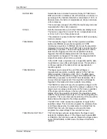
Entry 

Description 


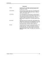
PROGRAM 1 

VOLTAGE 

Programs the output voltage in rms. when in AC mode or 
absolute voltage when in DC mode. In DC mode, negative 
values can be entered. 

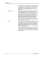
FREQ 

Programs the output frequency when in AC mode. If the unit is 
in DC mode, the value for FREQ will be set to DC and cannot be 
changed until AC mode is selected. When in AC mode, the 
frequency can be changed from 16 Hz to 500 Hz. Values 
entered that fall outside this range will generate a -200 RANGE 
ERROR and will not be accepted. 

VOLT RANGE 

Selects 135/150V or 270/300V voltage range. The actual range 
values may be different depending on the configuration. The 
value of this field can only be changed with the shuttle or the +/- 
key. 

Note 

that the voltage range is coupled with the output relay 

state on all i/iX AC sources with firmware revision 2.39 or 
higher.  If the output relay is closed (OUTPUT ON), the voltage 
range cannot be changed.  

CURR LIMIT 

Sets the current limit value for the current detection system. 
When the load current value exceeds the set current limit, a 
fault condition is generated. The actual response of the AC 
Source to a current limit fault is determined by the protection 
mode selected in the CONFIGURATION menu. (CC = Constant 
Current, CV = Constant Voltage). 

Содержание 10001i

Страница 1: ...0085 direct Fax 858 458 0267 Email Domestic Sales domorders sd ametek com International Sales intlorders sd ametek com Customer Service service ppd ametek com Web www programmablepower com March 2011...

Страница 2: ......

Страница 3: ......

Страница 4: ...ruments Models 3001i 5001i 5001i 400 9003i 10001i 10001i 400 15001i 15001i 400 15003i 15003i 400 30003i 30003i 400 3001iX 5001iX 5001iX 400 9003iX 10001iX 10001iX 400 15001iX 15001iX 400 15003iX 15003...

Страница 5: ...s only Notice of Copyright i Series iX Series AC Power Source User Manual 2010 AMETEK Programmable Power Inc All rights reserved Exclusion for Documentation UNLESS SPECIFICALLY AGREED TO IN WRITING AM...

Страница 6: ...ii This page intentionally left blank...

Страница 7: ...nnel and equipment safety Always ensure that facility AC input power is de energized prior to connecting or disconnecting any cable In normal operation the operator does not have access to hazardous v...

Страница 8: ...tructions of AMETEK is opened modified or disassembled in any way without AMETEK s consent or is used in combination with items articles or materials not authorized by AMETEK The Buyer may not assert...

Страница 9: ...Front Panel 37 4 2 Menu Structure 42 4 3 Output Programming 77 4 4 Waveform Management iX Series only 78 4 5 Standard Measurements 83 4 6 Advanced Measurements iX Series only 85 4 7 Transient Programm...

Страница 10: ...133 9 2 IEC 61000 4 11 Option 180 9 3 IEC 61000 4 13 Option 187 9 4 EOS Option 199 9 5 Mode iX Option 214 9 6 Omni Options 222 9 7 LNS Option and XLS Option 233 9 8 Option 704 MilStd704 Tests 239 9 9...

Страница 11: ...Figure 4 13 VOLTAGE SWEEP STEP SETUP screen 56 Figure 4 14 FREQUENCY SWEEP STEP SETUP screen 58 Figure 4 15 VOLTAGE FREQUENCY SWEEP STEP SETUP screen 59 Figure 4 16 START VIEW TRANSIENT SEQUENCE scree...

Страница 12: ...0 4 13 Menu 188 Figure 9 26 IEC 61000 4 13 FCurve 190 Figure 9 27 IEC 61000 4 13 OSwing 190 Figure 9 28 IEC 61000 4 13 Sweep 191 Figure 9 29 IEC 61000 4 13 Harmonics 192 Figure 9 30 IEC 61000 4 13 Int...

Страница 13: ...on Test Control Screen 261 Figure 9 65 704 Option EUT Measurement Data Screen 264 Figure 9 66 ABD Option Test Selection Screen 293 Figure 9 67 ABD Option Test Control Screen 297 Figure 9 68 ABD Option...

Страница 14: ...Table 9 3 Normal Voltage Unbalance 137 Table 9 4 Normal VoltageSurge Sequence 141 Table 9 5 Normal Frequency Transient Sequence 142 Table 9 6 Normal Frequency Variation Sequence 142 Table 9 7 Emergenc...

Страница 15: ...iption The 3001i 5001i 3001iX and 5001iX are high efficiency lightweight AC power sources that provide a precise output with low distortion Older generation i Series have two voltage ranges either 0 1...

Страница 16: ...440 VLL 10 400 400 480 VLL 10 400 3 phase 3 wire ground Line VA 5000VA 8000VA Line Current 25 A RMS max Per Box 23 A RMS max at 208 240 VAC 12 A RMS max at 400 440 VAC and 400 480 VAC Per Box Line Fr...

Страница 17: ...16 to 400 Hz DC mode 0 5 of range 0 5 of range DC offset AC DC mode 5 of range 0 1 VDC 25VDC 5 of range 1 VDC 25VDC Voltage Distortion 1 linear load 1 max THD at 50 60 Hz 2 max THD at 400 Hz 1 max THD...

Страница 18: ...7 270 VDC range 7 00 300 VDC range Current maximum rms amps per phase 5001 15003i iX per phase 37 0 135 VAC range 18 5 270 VAC range 37 0 135 VAC range 33 3 150 VAC range 18 5 270 VAC range 16 7 300 V...

Страница 19: ...38 8 270 VDC range 77 7 135 VDC range 70 0 150 VDC range 38 8 270 VDC range 35 0 300 VDC range Derated linearly from 50 of voltage to 10 of specified current at 5 of voltage range Note For the iX seri...

Страница 20: ...00 m Output Noise 20 kHz to 1 MHz 400 mVrms max 135 V range 800 mVrms max 270 V range 250 mV rms typ 500 mV rms max Peak Rep AC Current 3001i iX 5001i iX 9003i iX 15003i iX 110 A for 135 V range 92 A...

Страница 21: ...i and 15001i For 10001i and 15001i resolution decreases by factor of 10 ranges for current and power increases by factor of ten 2 1 4 AC Measurements iX series Parameter Range Accuracy Resolution Freq...

Страница 22: ...0 5 Voltage Fundamental 0 25V 0 01V Harmonic 2 50 0 25V 0 1 0 1 kHz 0 01V Current Fundamental 0 05A 0 01A Harmonic 2 50 0 05A 0 1 0 1 kHz 0 01A Accuracy specifications are times three for three phase...

Страница 23: ...voltage or frequency change Function strobe output can be reassigned as trigger output when running list transients This output requires a external DC supply and pull up resistor Remote Inhibit Also r...

Страница 24: ...and exhaust to the rear Internal Construction Modular sub assemblies Rear Panel Connections see section 3 for description of connections Input terminal block with cover Output terminal block with cove...

Страница 25: ...User Manual i Series iX Series 11 Parameter Specification Shock Designed to meet NSTA 1A transportation levels...

Страница 26: ...ys is used to move the cursor position in all menus This allows quick selection of the desired function or parameter Function keys Measure key will display most measurement values Program key will sho...

Страница 27: ...ut relay Three Phase Output 9003iX 15003Ix Three power sources with one controller in the Phase A power source The one controller controls all three outputs 15003iX LKM LKS Three power sources each wi...

Страница 28: ...BNC output with internal 9Vdc pull up for connection to external equipment such as oscilloscope Compatible with 3001i iX and 5001i iX Refer to section 3 6 5 TIS Function strobe break out box for syst...

Страница 29: ...r source weighs 61 lb 28kg Obtain adequate help when moving or mounting the unit 3 2 Power Requirements The 3001i iX AC Power Source has been designed to operate from a single phase 208 to 240 volt AC...

Страница 30: ...e input terminal block cover and strain relief must be installed in table top applications to maintain protection against hazardous voltages CAUTION Capacitors in the power source may hold a hazardous...

Страница 31: ...ce and the load Table 3 1 shows the AWG size of the cables that may be used Cable lengths must not exceed twenty five 25 feet For lengths greater than 25 feet calculate the voltage drop from the follo...

Страница 32: ...The connector is also used for the external sync input external modulation input and trigger output Table 3 2 System Interface Connector J22 J22 Description 1 Analog Common analog signal common 2 MR B...

Страница 33: ...change Isolated output that requires a pull up resistor 22K to 5 VDC Use J22 pin 14 F STB LO for common See section 3 6 5 for details 32 EX SYNC HI External Sync input HI This is an input that can be...

Страница 34: ...amage to the unit may result All 3001iX and 5001iX AC Sources are shipped with the sense connections wired to the output terminals This will prevent a voltage fault when the external sense mode is sel...

Страница 35: ...RS232 cable is required A 6 foot 2 meter long cable CI P N 7000 263 1 is supplied in the iX Series ship kit The wiring diagram for this cable is shown below in case a longer cable has to be construct...

Страница 36: ...High Function Strobe Common Centronics Connector System Interface 5 0 400 uS Figure 3 3 Function Strobe Connection When running list transients on the AC source the LIST TTLTrigger SCPI command may be...

Страница 37: ...of the output relay programmed from the front panel or the bus It may be used for safety interlock purposes A logic low on this pin will cause the output voltages to be programmed to 0 0 volts and the...

Страница 38: ...User Manual 24 i Series iX Series Figure 3 5 Rear Panel View for the 3001i 3001iX...

Страница 39: ...User Manual i Series iX Series 25 Figure 3 6 Rear Panel View for the 5001i 5001iX...

Страница 40: ...circuit breaker and indicator lights The units must all be connected with the system interface cable but not the clock and lock cables The HI outputs on all the terminal blocks should be connected to...

Страница 41: ...50 volts and current limit 20 0 amps 3001iX or 33 3 amps 5001iX Press ENTER 5 Enable the output by pressing the output on off button below the front panel display screen The green LED next to the butt...

Страница 42: ...User Manual 28 i Series iX Series Figure 3 7 Connection For Single Power Source 5001iX i 3001iX i...

Страница 43: ...User Manual i Series iX Series 29 Figure 3 8 Functional Test Setup...

Страница 44: ...User Manual 30 i Series iX Series Figure 3 9 Single Phase 10000 VA System 10001iX i...

Страница 45: ...User Manual i Series iX Series 31 Figure 3 10 Three Phase 15000 VA System 15003iX i LK Three Controllers...

Страница 46: ...User Manual 32 i Series iX Series Figure 3 11 Single Phase 15000 VA System 15001iX i...

Страница 47: ...User Manual i Series iX Series 33 Figure 3 12 Three Phase 15000 VA system 15003iX i One Controller...

Страница 48: ...User Manual 34 i Series iX Series Figure 3 13 Connection With MODE Option...

Страница 49: ...User Manual i Series iX Series 35 Figure 3 14 Two Phase 10000 VA System 10002i LK Two Controllers...

Страница 50: ...User Manual 36 i Series iX Series Figure 3 15 Three Phase 9000 VA System 9003iX i One Controller...

Страница 51: ...se Line input It will automatically trip when the input current rating of the unit is exceeded due to some component failure The contrasting black color and large size throw bar make it easy to locate...

Страница 52: ...t modes of operation MODE DESCRIPTION IMMEDIATE mode Any time the ENTER key is pressed the i iX Series returns to its normal mode of operation In this mode changes made with the shuttle knob or the da...

Страница 53: ...ly by pressing the PROG key WAVE The WAVE key is a shortcut to access the WAVEFORM screen directly The WAVEFORM screen is used to select a user defined arbitrary waveform iX Series only MEAS The MEAS...

Страница 54: ...used to toggle between these two values 4 1 6 DECIMAL KEYPAD The decimal keypad may be used to enter any numeric parameter required in any of the menu fields Several fields accept input from either th...

Страница 55: ...values for fields that have a resolution less than 1 The amount of resolution for each menu field is normally visible on the LCD If more digits are entered after the decimal point than can be accepted...

Страница 56: ...rements and Waveform In any case there are never more than three levels of menus although some menus may be spread across more than one screen 4 2 1 MAIN Menus Figure 4 7 Menu 1 through 3 The top leve...

Страница 57: ...ams that may be installed in the i iX Series AC source SETUP REGISTERS The SETUP REGISTERS menu allows complete instrument settings and transient list programs to be saved to nonvolatile memory MORE T...

Страница 58: ...MODE SCALE TRIG MODE TRIG SOURCE TRIG PHASE TRIG DELAY START TRANSIENTS VOLT SURGE SAG START VOLT SWEEP STEP START GO TO VOLT FREQ SWEEP STEP DURATION END VOLT DUR SCALE VOLT FREQ SWEEP STEP DURATION...

Страница 59: ...VOLT CURR CONTROL VOLT PAIR RS232 BAUDRATE PREVIOUS SCREEN OL MODE RS232 DATA INITIAL SETUP VOLTAGE TRIP DELAY RS232 PARITY LIMIT SETUP VOLTAGE CUR LIMIT VOLT SENSE RS232 STOPBITS MORE CUR LIMIT PREV...

Страница 60: ...ltage when in DC mode In DC mode negative values can be entered FREQ Programs the output frequency when in AC mode If the unit is in DC mode the value for FREQ will be set to DC and cannot be changed...

Страница 61: ...gle through these three selections In DC mode no frequency selection is possible and all maximum current and power ratings are divided by two The i Series offers AC or DC modes DC OFFSET When the AC D...

Страница 62: ...asurement screens can be reached by successively pressing the MEAS key which will toggle to all four available screens In three phase configuration iX Series measurements are available for each phase...

Страница 63: ...instantaneous peak current value detected at the output This value is updated continuously and does not require a reset operation like the PEAK CURR readout The instantaneous peak current does not use...

Страница 64: ...on trigger and display mode The actual data is displayed whenever the ENTER key is pressed while the cursor is on the VIEW or START field The following fields are available on this menu Figure 4 10 HA...

Страница 65: ...he data and is most appropriate for repetitive signals TRIG SOURCE The trigger source selects the event that will trigger a measurement acquisition Available options for this field are IMM immediate P...

Страница 66: ...itive trigger delays can exceed the length of the acquisition buffer in which case the trigger event itself will not be in the buffer any more The maximum value of the trigger delay is 1000 ms The def...

Страница 67: ...rt of the sag or surge VOLT SWEEP STEP Voltage sweeps cause the output voltage to change from the present value to a user specified end value at a specified rate of change A voltage step on the other...

Страница 68: ...set the voltage level during the transient duration in volts DUR SCALE Duration scale default is time in seconds Use the Shuttle knob to select CYCLES if desired Note that durations expressed in cycl...

Страница 69: ...ecution of this event in the list is required EVENT This must be the last item in the transient edit screen All data fields must be entered before inserting the EVENT The EVENT takes a value from 1 to...

Страница 70: ...E Duration scale default is time in seconds Use the Shuttle knob to select CYCLES if desired Note that durations expressed in cycles may cause rounding errors if the period of the selected frequency s...

Страница 71: ...e execution of this event in the list is required EVENT This must be the last item in the transient edit screen All data fields must be entered before inserting the EVENT The EVENT takes a value from...

Страница 72: ...ELAY This is the time delay the frequency will stay at END FREQ before it proceeds with the next transient event or completes the transient FUNCTION iX Series only This field can be used to select the...

Страница 73: ...frequency for the event A duration of 0 seconds will cause the output voltage and frequency to reach their end value immediately END FREQ This is the output frequency at the end of the transient even...

Страница 74: ...ld and the ENTER key is pressed transient execution starts The output relay must be closed or an error message will appear and the transient will not start Once a transient is in progress this field c...

Страница 75: ...Note that changing the distortion level of the CLIPPED sinewave while the CLIPPED sinewave is used on the output of one or more phases forces the output of the AC Source to be dropped momentarily To a...

Страница 76: ...moved to this field the ENTER key will execute the selected MODE If the mode is set to PROG pressing ENTER while the cursor is on the SQUARE entry will select the square wave for the phase shown in th...

Страница 77: ...selected MODE If the mode is set to PROG pressing ENTER while the cursor is on the user defined entry will select the custom waveform for the phase shown in the top right corner of the display If the...

Страница 78: ...found in the APPLICATIONS menu Entry Description MIL STD 704 Test sequence for MIL standard 704 AC and DC tests OMNI OPTION This entry selects the OMNI control menu The OMNI option provides a lumped r...

Страница 79: ...o confirm the save operation RECALL REGISTER Recall instrument setup from a register number selected by the user The numeric data entry keypad should be used to enter a number between 0 and 7 Once the...

Страница 80: ...ain the set voltage at the output until the load current exceeds the current limit setting at which time the voltage will be dropped to zero This effectively shuts off the AC source output in case of...

Страница 81: ...mits are hardware determined and cannot be changed by the user They are shown for reference only UTILITY 2 CONFIGURATION The Configuration menu shows the installed options This screen is for reference...

Страница 82: ...er 9600 19200 or 38400 baud The baudrate set on the AC source must match the one programmed for the communications port of the controller RS232 DATA This field is used to set the number of databits to...

Страница 83: ...er the trip delay time to maintain the level of programmed current The constant voltage mode will maintain the set voltage as long as the current drawn by the load does not exceed the current limit pr...

Страница 84: ...ided in the INITIAL SETUP menus Entry Description INITIAL SETUP 1 VOLTAGE Sets the power on AC voltage for AC and AC DC modes or the DC voltage for DC mode CURR LIMIT Sets the power on current limit v...

Страница 85: ...change groups you must change this field to the desired new group and cycle the power to the AC source or issure a RST command over one bus CLOCK MODE Sets the clock source used at power up Available...

Страница 86: ...s provided on this screen Entry Description VOLTAGE Maximum AC rms or DC voltage available in the high voltage range CUR LIMIT Maximum AC rms current limit available in the low voltage range FREQ LO L...

Страница 87: ...Series models this field is always set to ON to indicate the advanced capabilities for waveform generation and measurement analysis are present On i Series AC sources this field is always set to N A n...

Страница 88: ...he OUTPUT IMPEDANCE menu can be accessed from MENU 3 The following fields are available in this menu Entry Description RESISTIVE Sets the resistive component of the output impedance This value can be...

Страница 89: ...on performing a calibration The following calibration factors are available from this menu Entry Description VOLT FS Full scale voltage measurement calibration factor VOLT 0 Zero offset voltage measur...

Страница 90: ...oltage output calibration factor V HI FREQ High frequency full scale voltage output calibration factor VOLT ZERO Zero offset voltage calibration factor PHASE OFST Phase offset calibration factor Compe...

Страница 91: ...default mode of operation is an immediate mode in which changes to output parameters made with the knob or the entry keypad are immediately reflected at the output To change the output voltage Counter...

Страница 92: ...he FREQ field will be blinking to indicate a change in settings but the output remains unchanged 8 Press the ENTER key Both new voltage and frequency output values are now present at the output The un...

Страница 93: ...ected for each phase The number of custom waveforms from which to select remains 50 but each phase can be assigned a different custom or standard waveform The specific output phase for which the waves...

Страница 94: ...ceed as follows 1 Press the MENU key three times to select the MENU 3 screen 2 Move the cursor to the UTILITY entry end press ENTER You are now in the UTILITY 1 menu 3 Move the cursor to the INITIAL S...

Страница 95: ...age The figure shown here illustrates the relationship between the crest factor of the waveshape or its peakiness and the maximum peak voltage allowed for a given voltage range Since the peak voltage...

Страница 96: ...forms can be switched as part of the transient system Each transient type setup menu has a FUNCTION field This field allows selection of any of the standard or custom waveforms available in the select...

Страница 97: ...screens are available Mode AC DC AC DC MEASUREMENTS 1 VOLTAGE AC rms voltage DC Voltage AC rms voltage CURRENT AC rms current DC Current AC rms current FREQUENCY Frequency n a Frequency POWER Real po...

Страница 98: ...C source for measurement purposes always consider these specifications when interpreting results Measurement inaccuracies become more pronounced as the signal being measured is at the low end of the m...

Страница 99: ...ults 4 Move the cursor to the DATA MODE field and select ABS or REL Absolute display mode will show all harmonic components in volts or amps Relative display mode will use the fundamental as a 100 ref...

Страница 100: ...in numeric form to the left for the currently selected harmonic component The display can show up to 24 components at a time The triangle at the bottom of the display shows the currently selected comp...

Страница 101: ...o see at least one cycle of the output waveform If the output is programmed at 50 Hz a 20 ms scale would display exactly one signal period 6 Move the cursor to the TRIG MODE and select SINGLE or CONT...

Страница 102: ...he data under the vertical cursor This cursor is a dotted line that can be moved using the knob If the left or right edge of the display window is reached the entire display will shift so the cursor a...

Страница 103: ...uired and the LCD display is updated No user intervention is required after the initial START event This mode is appropriate for capturing repetitive events or to monitor the source output continuousl...

Страница 104: ...lue specified and it triggers the measurement acquisition at the same moment in time When selecting this trigger source the field below the TRIG SOURCE field changed to SET VOLT Use this field to ente...

Страница 105: ...inrush current can be captured under worst case conditions In this case the voltage should be programmed to 0 volt before triggering the acquisition using the START field Note When using the SET VOLT...

Страница 106: ...4 37 where a 20 ms trigger delay is used after triggering on phase A 180 The fundamental frequency of the output is 50 Hz The trigger point is indicated by the dashed line It occurs on the first 180...

Страница 107: ...delay was set a 20 ms Notice that the data acquisition window now contains data that occurred before the user pressed the ENTER key to start the acquisition START ENTER TRIG SOURCE PHASE 0 ACQUISITIO...

Страница 108: ...bus On power up the AC source always reverts to the maximum slew rate for both voltage and frequency 4 7 2 Using Transient Modes The voltage can be programmed in the following transient operating mode...

Страница 109: ...ired to set up a Pulse transient include the pulse count pulse period and pulse duty cycle An example of a Pulse transient is shown in Figure 4 39 In this case the count is 4 the pulse period is 16 6...

Страница 110: ...list specifies the pulses as three voltage points point 0 2 and 4 each with its corresponding dwell point The intervals are three zero voltage points point 1 3 and 5 of equal intervals The count param...

Страница 111: ...ber from 1 through 99 The transient list will be executed in order of event number Leaving a gap between event numbers allows you to insert events at different places later in the sequence Deleting ev...

Страница 112: ...rts to ABC Frequency transients are identical to voltage transients except they apply to all three phases at all times in a three phase configuration 4 7 6 Programming Slew Rates As shown in the previ...

Страница 113: ...d without the output of the source being turned off For three phase configurations each phase has its own waveform list so different waveforms may be programmed on different phases during transient ex...

Страница 114: ...may be useful when running slowly changing output transients to hold the output at a specific setting while observing the effect on the unit under test 4 7 9 Saving Transient List Programs When the A...

Страница 115: ...3001iX and 5001iX is given in this section Refer to Figure 5 1 for a block diagram of the system Figure 5 2 shows the system interconnect OUTPUT AC CHOKE POWER BOARD AC BULK I O CAPS LOGIC BOARD DC P...

Страница 116: ...nd 500 volts for the 270 300 VAC output The oscillator assembly generates the reference waveforms and provides frequency amplitude and impedance control The current limit board in conjunction with the...

Страница 117: ...board that is used for a shuttle input 5 3 3 Phase B and C Board This assembly A8 has the waveform measurement and impedance programming components for the Phase B and C outputs This board is only ins...

Страница 118: ...User Manual 104 i Series iX Series Figure 5 2 Power Source Module Block Diagram...

Страница 119: ...he output voltage and put the entire system into the constant current mode 5 5 Auxiliary Power Supply The auxiliary power supply is mounted on the DC DC power board This assembly generates nine low vo...

Страница 120: ...imit and overvoltage protection When the output of the DC converter is up and in regulation the LED on the input output board will be lit The LED can only be seen by looking directly down between the...

Страница 121: ...User Manual i Series iX Series 107 Figure 5 3 5001i Internal Layout...

Страница 122: ...User Manual 108 i Series iX Series Figure 5 4 Logic Board LED s...

Страница 123: ...capacitors on the AC power board to provide a precision low frequency 16 500 Hz output See Figure 5 3 and Figure 5 5 Three isolated 18V supplies provide power for the gate drives The 18V is regulated...

Страница 124: ...User Manual 110 i Series iX Series Figure 5 5 AC Power Stage Layout...

Страница 125: ...User Manual i Series iX Series 111 Figure 5 6 AC Control Logic Block Diagram...

Страница 126: ...480 VAC AND 700 VDC ARE PRESENT IN CERTAIN SECTIONS OF THIS POWER SOURCE THIS EQUIPMENT GENERATES POTENTIALLY LETHAL VOLTAGES DEATH ON CONTACT MAY RESULT IF PERSONNEL FAIL TO OBSERVE SAFETY PRECAUTIO...

Страница 127: ...otek Model RUG Z R010 0 1 or equivalent 1 milliohm Current Shunt Isotek Model RUG Z R001 0 1 10001i iX 15001i ix and 15003iX MODE Load Bank Various high power load resistors will be needed Computer Op...

Страница 128: ...alibration section of the manual For the AC Output Calibration either the Fluke 8506A or HP 34401A may be used If the HP 34401A is used it must be put into the slow filter mode Note For purposes of ca...

Страница 129: ...the 300 VAC Range by pressing and selecting the 300 Range with the shuttle Go the OUTPUT CAL screen select the VOLT ZERO parameter and adjust the output to 0 0 0 005 VDC 300 VAC Range Volt Full scale...

Страница 130: ...be calibrated by pressing the PHASE key TITLE PROGRAM VALUES CALIBRATION VALUE ADJUST TO 150 VAC range DC Zero 150 range 0 0 V VOLT ZERO 0 5 mv DC 150 VAC range Volt FS 120 0 V 60 Hz VOLT FS 120 0 05...

Страница 131: ...current shunt in series with the load to measure the AC and DC load current When programming a DC load always program the output voltage to 0 volts before changing the output load This will prevent lo...

Страница 132: ...User Manual 118 i Series iX Series Figure 6 2 Test Equipment Hook up for Measurement Calibration...

Страница 133: ...ogram the 150 volt range and 0 volts Apply a 67 ohm 270 watt load to the output This resistor will represent approximately a 2 amp load Program the output to 135 volts Enter the actual DC load current...

Страница 134: ...3 0 VDC do nothing For multiphase power systems with one controller 15003iX the adjustment for Phase B and C must be made to R14 on the Current Limit Board for the power source of the respective phase...

Страница 135: ...included in the 32 bit Cigui32 program however The calibration for impedance can be found in the Calibration Menu on the main CIGUI screen In this case the GPIB interface must be connected to the PC t...

Страница 136: ...ive portion it may be necessary to tweak the adjustment pots on the iX controller These pots were originally adjusted at the factory and normally do not have to be adjusted again The Full Scale calibr...

Страница 137: ...o volts and turn the Output ON 2 On the current limit board monitor TP5 with respect to TP1 Adjust R23 on the input output board for 0 0 mVDC 0 5 mVDC CAUTION Use extreme care in adjusting R23 Do not...

Страница 138: ...User Manual 124 i Series iX Series Figure 6 3 Adjustment Location...

Страница 139: ...fied electronic technician should attempt this level troubleshooting 7 3 Basic operation Table 7 1 Basic Symptoms PARAGRAPH PROBLEM 7 3 1 Excessive Output Voltage 7 3 2 Poor Output Voltage Regulation...

Страница 140: ...SE SOLUTION Input circuit breaker switched off Switch the breaker on No input power to TB3 Ensure 3 phase power is getting to TB3 Unit tripped on overvoltage or overcurrent Turn circuit breaker off wa...

Страница 141: ...LT IF PERSONNEL FAIL TO OBSERVE SAFETY PRECAUTIONS DO NOT TOUCH ELECTRONIC CIRCUITS WHEN POWER IS APPLIED 7 4 1 Switch Off Unit Switch of the unit at the circuit breaker on the front panel as well as...

Страница 142: ...to the factory for exchange or repair If a low resistance is not found replace the fuse and carry on with the check procedure 7 4 5 Power on Troubleshooting Using the LED s If no fuses were blown or i...

Страница 143: ...Board are lit and there is still no output then there may be no output from the oscillator To check the oscillator output turn off the unit at the main breaker Set the DVM to AC volts and connect the...

Страница 144: ...ch socket driver remove the four bolts that hold the AC power module heatsink There is one bolt at each corner Carefully remove all the hardware from the unit The AC power module can now be unplugged...

Страница 145: ...BOARD PC ASSEMBLY 3001iX CI 1 A4 7000 732 2 LOGIC BOARD PC ASSEMBLY 5001iX CI 1 A6 7000 724 1 CURRENT LIMIT PC ASSEMBLY CI 1 2 7000 43 8 11 THRU 30 PROGRAMMABLE OSC FRONT PANEL ASSY CI 1 A10 7000 727...

Страница 146: ...50 vac quick acting F9 270174 1 amp 250 vac quick acting F10 270183 3 amp 250 vac quick acting F11 270182 10 amp 250 vac time lag AC POWER ASSY 7000 730 F1 270199 50 amp 700 vac very quick acting 240...

Страница 147: ...erage for revision D in the software as the CIGui32 program is designed to support all revisions For now revision D has no associated data files in the CIGui32 9 1 1 Option 160 RTCA DO160 rev D Tests...

Страница 148: ...test Group 2 and 3 only DC Source 1 Normal State Voltage test 2 Momentary Power Interrupt Undervoltage test 3 Voltage Surge and Under 9 1 1 3 2 EMERGENCY TEST AC Source 1 Emergency Voltage and Frequen...

Страница 149: ...he APPLICATIONS screen will appear as shown in Figure 9 1 Figure 9 1 Application Menu Scroll to the RTCA DO 160D entry using the up and down cursor keys Press the ENTER key to select the RTCA DO 160D...

Страница 150: ...above tests can be selected by scrolling to the highlighted selection using the up and down key and the ENTER key to start the selected test For some of these tests numeric data entry may be required...

Страница 151: ...balance This test will change the output voltage for each phase from 115 volts to 115V offset Refer to Table 9 3 for the offset value and the Frequency The test will last 30 minutes The test will be r...

Страница 152: ...User Manual 138 i Series iX Series Figure 9 4 Voltage Modulation...

Страница 153: ...es a numeric value equal to the modulation rate in Hz This value must be between 0 01 Hz and 100 Hz The frequency modulation is calculated based on the modulation rate as defined in Figure 9 5 This te...

Страница 154: ...DO160 Table 16 1 Test conditions for equipment with digital circuits NOTES 1 Definitions T1 Power interrupt time T2 Time it would take for the applied voltage to decay from V nom to zero volts T3 Time...

Страница 155: ...he test the power source will be switched back to the low range automatically Voltage Time Seq No RTCA Group 1 Group 2 Group 3 ALL 1 115 115 115 115 5 Minute 2 160 160 160 170 30msec 3 115 115 115 115...

Страница 156: ...Normal Frequency Variation Sequence This test will apply to Group 2 and 3 only At 115 voltage the frequency is set to 360Hz for 5 minutes The frequency is slowed per sequence listed in Table 9 6 The...

Страница 157: ...from Table 9 7 The key backspace will terminate the test at any time VOLT FREQ MAX This test will set the voltage and frequency for a level defined by Table 9 8 The test will last for 30 minutes The t...

Страница 158: ...VOLT MAX Standard Group RTCA Group1 Group2 Group3 Voltage 1 97 97 104 97 97 3 98 5 98 5 105 5 98 5 98 5 Frequency 400 400 370 360 360 Table 9 10 Abnormal Voltage Minimum Standard Group RTCA Group1 Gro...

Страница 159: ...r source is set at the low voltage range the high voltage range will be selected before the test starts At the end of the test the AC source will be switched back to the low range The output voltage w...

Страница 160: ...screen The screen will appear as shown in Figure 9 11 Figure 9 11 Normal State The DO 160 NORMAL screen has the following tests 1 VOLT MIN 2 VOLT MAX 3 VOLT UNDER 4 VOLT SURGE 5 POWER INTERRUPT The ab...

Страница 161: ...equipment The output voltage will drop to 10 volts and will ramp up at a rate of 0 15 volt sec for the US standard and at a rate of 0 30 volt sec for EUROCAE standard for 30 seconds before it returns...

Страница 162: ...t will change the output voltage from 28V or 14V to 20 5V or 10V The test will last for 30 minutes The key backspace will terminate the test at any time VOLT MAX This test will change the output volta...

Страница 163: ...equipment Category Surge 1 Surge 2 Volt Dwell msec Volt Dwell msec A 46 3 100 37 8 1000 B 60 100 40 1000 Z 80 100 48 1000 Table 9 16 Abnormal Voltage Surge 9 1 1 6 3 Emergency Test The Emergency test...

Страница 164: ...Custom Tests 9 1 2 12 Test Tables 9 1 2 13 160 Option Related Error Messages 9 1 2 1 General The 160 option supports RTCA DO 160 rev E Section 16 voltage and frequency immunity tests in either of the...

Страница 165: ...e required as indicated The extent of coverage of the 160 option as implemented on the iX Series platform is shown in the table below Tests marked with an x generally require additional hardware to be...

Страница 166: ...al Voltage 16 5 1 6 Normal Frequency Variations N A X X 16 6 2 2 Low Voltage Conditions N A N A 16 5 1 7 Voltage DC Content X X 16 6 2 3 Momentary Under Voltage Operation 16 5 1 8 Voltage Distortion P...

Страница 167: ...by 8Hz Resolution 115VAC A NF 16 5 1 3 360Hz mod by 75Hz 360Hz mod by 8Hz Resolution 115VAC A NF 16 5 1 3 650Hz mod by 75Hz 650Hz mod by 8Hz Resolution 115VAC A WF 16 5 1 3 360Hz mod by 75Hz 360Hz mod...

Страница 168: ...the top of the screen 10 Verify that the test sequence and description shown in the table on the Test Control screen is indeed the desired test 11 Click the Start button to initiate the test 12 Observ...

Страница 169: ...tes ac equipment intended for use on aircraft electrical systems where the primary power is from narrow variable frequency 360 to 650 Hz ac system A WF designates ac equipment intended for use on airc...

Страница 170: ...e each tab Tab Description Test Selection This tab allows the operator to select the library of test files to use Select Airframe and the relevant Power group It also displays the AC power source sett...

Страница 171: ...ile without using the Test Selection table tab Save Saves the contents of the test sequence data grid to the selected test file Save As Saves the contents of the test sequence data grid to a user defi...

Страница 172: ...the new selection The first test section of the table will automatically be selected when switching power groups Present Power Source Output Settings This section displays the programmed steady state...

Страница 173: ...ent this test section on the power source User Data The area at the bottom of this tab may be used to enter general information regarding the unit under test the test location and operator and environ...

Страница 174: ...The execution options determine the mode of operation when the Start button is clicked Available execution modes and settings are Execute all steps In this mode all steps in the test sequence will be...

Страница 175: ...execution Table Header The table header is shown against a yellow background and shows the table from which this test sequence was selected Test Sequence Data Grid The test sequence data grid displays...

Страница 176: ...s power source To test to the full 150 KHz range an external audio generator and coupling transformer as outlined in RTCA DO160 Section 18 Figure 18 1 is required The DO160 DC Ripple test screen is av...

Страница 177: ...a is shown for all three phases For single phase EUT data is shown for phase A only as long as the power source is in single phase mode The top half of the Parameters tab displays all parametric measu...

Страница 178: ...ry of the GUI application directory using file name convention MeasData_DO160_nnn_Hz txt where nnn is the frequency setting or DC Waveforms This tab displays the voltage and current waveform time doma...

Страница 179: ...n is always available regardless of what sub tab is selected Settings Brings up a dialog box that allows scaling and color changes for the Waveform or Current harmonics graphs Note that setting change...

Страница 180: ...iles Tests can be customized as needed by editing these table configuration and test sequence files To do so create a new subdirectory under the application directory To access any new sub directory f...

Страница 181: ...1 5 Normal Transients ac 16 5 1 5 1 Normal Voltage Surge ac 160V to 70V 400 Hz EACF115_NVSUR 16 5 1 5 2 Normal Frequency Surge ac 115V 350Hz to 400Hz EACF115_NFSUR 16 5 1 7 Voltage DC Content ac 16 5...

Страница 182: ...rruptions ac 650Hz nom Other Equipment EANF115_PINTC650 16 5 1 4d Momentary Power Interruptions ac Table 16 2 Additional Requirement Var Freq EANF115_PINTD 16 5 1 5 Normal Transients ac 16 5 1 5 1 Nor...

Страница 183: ...ly for 7 seconds each test EANF115_VUND650 16 5 2 3 Abnormal Transients ac 16 5 2 3 1 Abnormal Voltage surge 148V to 180V 360Hz Figure 16 5 apply at 10 sec intervals EANF115_AVSUR360 16 5 2 3 1 Abnorm...

Страница 184: ...rcuits EAWF115_PINTB800 16 5 1 4c Momentary Power Interruptions ac 360Hz nom Other Equipment EAWF115_PINTC360 16 5 1 4c Momentary Power Interruptions ac 800Hz nom Other Equipment EAWF115_PINTC800 16 5...

Страница 185: ...ary Undervoltage ac 10V and 60V 360Hz Apply for 7 seconds each test EAWF115_VUND360 16 5 2 2 Momentary Undervoltage ac 10V and 60V 800Hz Apply for 7 seconds each test EAWF115_VUND800 16 5 2 3 Abnormal...

Страница 186: ...2 EADC28_VRIP 16 6 1 3b Momentary Power Interruptions dc Table 16 3 Equipment with Digital Circuits EADC28_PINTB 16 6 1 3c Momentary Power Interruptions dc Other Equipment EADC28_PINTC 16 6 1 4 Normal...

Страница 187: ...ital Circuits EBDC28_PINTB 16 6 1 3c Momentary Power Interruptions dc Other Equipment EBDC28_PINTC 16 6 1 4 Normal Transients dc 16 6 1 4b Normal Voltage Surge dc 47V to 17V EBDC28_NVSUR 16 6 1 5 Engi...

Страница 188: ...rruptions dc Table 16 3 Equipment with Digital Circuits EZDC28_PINTB 16 6 1 3c Momentary Power Interruptions dc Other Equipment EZDC28_PINTC 16 6 1 4 Normal Transients dc 16 6 1 4b Normal Voltage Surg...

Страница 189: ...Normal Transients ac 16 5 1 5 1 Normal Voltage Surge ac 320V to 140V 400 Hz EACF230_NVSUR 16 5 1 5 2 Normal Frequency Surge ac 230V 350Hz to 400Hz EACF230_NFSUR 16 5 1 7 Voltage DC Content ac 16 5 1 7...

Страница 190: ...ADC14_VRIP 16 6 1 3b Momentary Power Interruptions dc Table 16 3 Equipment with Digital Circuits EADC14_PINTB 16 6 1 3c Momentary Power Interruptions dc Other Equipment EADC14_PINTC 16 6 1 4 Normal Tr...

Страница 191: ...al Circuits EBDC14_PINTB 16 6 1 3c Momentary Power Interruptions dc Other Equipment EBDC14_PINTC 16 6 1 4 Normal Transients dc 16 6 1 4b Normal Voltage Surge dc 23 5V to 8 5V EBDC14_NVSUR 16 6 1 5 Eng...

Страница 192: ...rruptions dc Table 16 3 Equipment with Digital Circuits EZDC14_PINTB 16 6 1 3c Momentary Power Interruptions dc Other Equipment EZDC14_PINTC 16 6 1 4 Normal Transients dc 16 6 1 4b Normal Voltage Surg...

Страница 193: ...slew time set This error can result in single step mode if the steps are executed out of order or one or more steps are skipped The voltage frequency values may no longer line up Try running the test...

Страница 194: ...standard Files applicable to Edition 2 0 have ED20 in their file name Do not mix these files as the data setup will not be correct if you do To load a test file select the Mode Dips or Vars and test...

Страница 195: ...creen from the MENU 2 screen The APPLICATIONS screen will appear as shown in Figure 9 17 Figure 9 17 Application menu Scroll to the IEC 1000 4 11 entry using the up and down cursor keys Press the ENTE...

Страница 196: ...tion due to a temperature or over current fault EOS STATE This field can have one of three values N A Indicates no EOS option is present or the EOS option was not powered up when the STATE was enabled...

Страница 197: ...135 3 at diff 10 19 70 10 90 135 180 3 at diff 10 20 70 25 180 225 270 3 at diff 10 21 70 50 270 315 0 3 at diff 10 Table 9 19 Dips and Interruptions Tests Performed During RUN ALL The user can chang...

Страница 198: ...End V in of UT Delay between steps s 1 VSweep 100 2 40 0 2 Hold 40 1 40 0 3 VSweep 40 2 100 10 4 VSweep 100 2 40 0 5 Hold 40 1 40 0 6 VSweep 40 2 100 10 7 VSweep 100 2 40 0 8 Hold 40 1 40 0 9 VSweep 4...

Страница 199: ...age Values must be entered in seconds The timing of voltage variations is different between editions 1 0 and 2 0 of the IEC 61000 4 11 test standard While the original standard used voltage ramps on b...

Страница 200: ...s are distributed with the CIGui32 program for both editions of the test standard Files applicable to Edition 2 0 have ED20 in their file name Do not mix these files as the data setup will not be corr...

Страница 201: ...ystems to ensure the correct firmware is provided The firmware revision is displayed on the LCD screen immediately after power up for a few seconds It can also be queried over the bus using the IDN co...

Страница 202: ...IEC 61000 4 13 Screen Parameters The IEC 61000 4 13 screen has the following common fields for all IEC 61000 4 13 test groups STATE The STATE field must be set to ON before the test can run Initial s...

Страница 203: ...oup if run group is selected The field has the following groups 1 FCURVE This is the first part of harmonic combination test 2 OSWING This is the second part of harmonic combination test 3 SWEEP This...

Страница 204: ...G group is selected the screen will appear as shown in Figure 9 27 The screen has the following parameters that are unique to the group Figure 9 27 IEC 61000 4 13 OSwing 1 LEVEL The level of the harmo...

Страница 205: ...individual range sweep is possible by selecting the desired range and selecting RUN RANGE from the RUN field 3 STEP The step size defines the inter harmonics sweep points Step size is fixed for the e...

Страница 206: ...levels the test state must be off and user class must be selected 2 HARM NO Selecting a harmonic number using the shuttle knob will allow examination of the LEVEL and PHASE of each harmonic and chang...

Страница 207: ...required to change the level An individual range step can be run by selecting the desired range followed by RUN RANGE from the RUN field 3 STEP The step size defines the inter harmonics sweep points T...

Страница 208: ...The STEP size can be changed when the test state is off 4 PAUSE Sets the time in seconds for which the test will pause between ranges There is only one value for the entire test The PAUSE can be set...

Страница 209: ...2 required Meister curve required Any functional anomalies Any functional anomalies Any functional anomalies Test Completed FAIL RecordResults Test Completed PASS RecordResults Yes Yes No Perform 8 2...

Страница 210: ...functional anomalies Any functional anomalies Test Completed FAIL RecordResults Test Completed PASS Record Results Yes Perform 8 2 2 Test Frequency Sweep Perform 8 2 4 Test Meister Curve Perform 8 2 3...

Страница 211: ...the RUN parameter with the shuttle knob and press the ENTER key The tests will run in the following sequence FCURVE OSWING SWEEP HARM IHARM MCURVE Note The test for class 3 will take about 25 minutes...

Страница 212: ...MONICS SCREEN The inter harmonics screen will appear as shown in Figure 9 35 This screen has the following parameters Figure 9 35 INTERHARMONICS SCREEN 1 REFERENCE This field will enable the Inter har...

Страница 213: ...option option 411 to perform IEC1000 4 11 voltage dips and interruptions tests The 411 option must be installed in the iX I power source for the EOS to function It is configured if the EOS was ordered...

Страница 214: ...e 100 270 VRMS Regulation 5 100 output 7 80 output EOS Gen 2 only 7 70 output 10 40 output Over Undershoot 5 into a 100 ohm resistive load Rise Fall Times Between 1 s 5 s into a 100 ohm resistive load...

Страница 215: ...ult lamp 9 4 4 4 Mechanical Dimensions 7 H x 19 W x 24 D 178 mm H x 483 mm W x 610 mm D Weight EOS 1 70 lbs 32 kg EOS 3 160 lbs 73 kg Connectors Input mains IEC 320 Source Compression Load Compression...

Страница 216: ...ages up to 600 VAC are available in certain sections of this product This equipment uses potentially lethal voltages DEATH On contact may result if personnel fail to observe safety precautions Do not...

Страница 217: ...Reinstall the carrier into the input module so that the desired voltage range appears in the module cover window Close the cover Note that attempting to operate the EOS from an input range that does...

Страница 218: ...recommended sequence between the iX source and the equipment under test For systems that do not include all the instruments shown maintain the sequence of the remaining instruments Note also that for...

Страница 219: ...User Manual i Series iX Series 205 Figure 9 36 Example Connection With 5001iX and EOS 1...

Страница 220: ...User Manual 206 i Series iX Series Figure 9 37 Example Connection With Compliance Test System and EOS 1...

Страница 221: ...User Manual i Series iX Series 207 Figure 9 38 15003iX CTS EOS3 LR3...

Страница 222: ...User Manual 208 i Series iX Series Figure 9 39 15003iX 3 EOS3...

Страница 223: ...vate the EOS unit An attempt to do so will indicate Error 222 Data out of range IEC 1000 4 11 tests may still be run but in pre compliance mode with the EOS unit bypassed Note that while the EOS is en...

Страница 224: ...ade using a toggle switch on the front panel of the EOS1 If this toggle switch is not present the EOS1 is a first generation version See Table 9 21 for revision details To use the 70 dip level set the...

Страница 225: ...f the 15003iX power source from the EOS input 2 With the EOS3 completely disconnected remove the top cover by removing the Phillips screws of the top cover 3 Each transformer one per phase has five ou...

Страница 226: ...User Manual 212 i Series iX Series Figure 9 40 EOS3 Location of 70 80 Taps for each phase Lug 3 70 Lug 5 80...

Страница 227: ...wer sources etc before cleaning Do not spray water or other cleaning agents directly on the instrument 9 4 7 2 Fuses There are two fuses used in the EOS 1 or EOS 3 They are located in the mains connec...

Страница 228: ...switching action is performed automatically via a control signal from the power system to the Mode iX phase mode controller 9 5 2 Specifications 9 5 2 1 Input Line Voltage user configurable 115 VAC 10...

Страница 229: ...C 320 Phoenix Contact HDFK10 Phoenix Contact HDFK50 Phoenix Contact HDFK10 System Interface 3M 3367 1000 mates with 3M 3366 1001 Chassis Slide General Devices C300S 118 U B308 BKT 9 5 2 5 Environmenta...

Страница 230: ...ages up to 600 VAC are available in certain sections of this product This equipment uses potentially lethal voltages DEATH On contact may result if personnel fail to observe safety precautions Do not...

Страница 231: ...lid into the IEC 320 module The power source to the Mode iX must provide protective earth grounding 9 5 3 3 Mechanical Installation The Mode iX has been designed for rack mounting in a standard 19 inc...

Страница 232: ...Manual 218 i Series iX Series Note The SOURCE and LOAD terminals of Mode iX will be at the hazardous live potentials of the iX series power sources driving it even if Mode iX box has not been switche...

Страница 233: ...User Manual i Series iX Series 219 Figure 9 41 Example Connection With MODE iX...

Страница 234: ...the phase mode controller between three phase and one phase mode The function of this switch is normally disabled and switching is remotely controlled via a signal on the system interface connector On...

Страница 235: ...ces etc before cleaning Do not spray water or other cleaning agents directly on the instrument 9 5 5 2 Fuses There is one fuse used in the Mode iX phase controller It is located in the mains connector...

Страница 236: ...and 3 18i Omni 1 37i 1 37iJ and 3 37i Line Voltage user configurable 115 VAC 10 or 230 VAC 10 115 VAC 10 or 230 VAC 10 Line Current 0 25 amps at 115 VAC input 0 125 amps at 230 VAC input 1 0 amps at 1...

Страница 237: ...OMNI 1 37iJ OMNI 3 37i 31 lb 14 kg 37 lb 17 kg 55 lb 25 kg 55 lb 25 kg Connectors Input AC Impedance Network Input and Output System Interface IEC 320 Kulka 9 85 series 3M 3367 1000 mates with 3M 336...

Страница 238: ...a small screwdriver 3 Pull out fuse holder prying with a screwdriver will be necessary 4 Orient the red fuse holder so that the desired voltage shows through the window It is necessary that the fuse a...

Страница 239: ...rnal Sense Wiring The external sense wires of the power source must be connected at the output of the power source and NOT at the output of the OMNI or at the load If the external sense wires were con...

Страница 240: ...User Manual 226 i Series iX Series Figure 9 42 Example Connections With OMNI 1 18i...

Страница 241: ...User Manual i Series iX Series 227 Figure 9 43 Example Connections With OMNI 3 18i...

Страница 242: ...User Manual 228 i Series iX Series Figure 9 44 Schematic Showing OMNI 1 37i and1 37iJ Connected to 5001iX System...

Страница 243: ...User Manual i Series iX Series 229 Figure 9 45 Schematic Showing OMNI 3 37i Connected to 30003iX System...

Страница 244: ...NI unit the BYPASS mode must be selected when the power source is operated on low output voltage range or if currents in excess of OMNI ratings will be drawn Bypass relays are provided to short out th...

Страница 245: ...e The output of the AC source will drop for about 50 ms when the OMNI MODE changes state To Bypass the OMNI turn the Shuttle Knob counterclockwise 9 6 6 4 Programmed Control The FLICKER BYPASS mode ma...

Страница 246: ...power to the OMNI before performing any of these steps Hazardous voltages may be present internally from the AC mains and from AC power source connected to the OMNI rear panel 1 Disconnect all source...

Страница 247: ...owing specifications The specifications shown here are for these line sync options only All other power source specifications for i Series and iX Series power systems are covered in their respective d...

Страница 248: ...to keep the iX output frequency locked to the line frequency There is a finite phase offset however between the iX source output and the line input to the iX power source This phase offset will vary...

Страница 249: ...User Manual i Series iX Series 235 9 7 4 Mechanical Dimensions Figure 9 49 XLS Module Dimensions...

Страница 250: ...ge connections between the XLS module the i iX Series master power source and the AC Line synchronizing voltage Figure 9 50 XLS Connection on Low Range 5001iX POWER SOURCE AC INPUT SYSTEM INTERFACE 80...

Страница 251: ...Series 237 Figure 9 51 XLS Connection on High Range 5001iX POWER SOURCE AC INPUT SYSTEM INTERFACE 80 250V COM 250 500V 250 500V SYNC INPUT FROM iX SOURCE INPUT OR OTHER AC LINE VOLTAGE 7000 262 2 sys...

Страница 252: ...ase input signal from the line To turn the sync mode back off set the CLK MODE field back to INT Over the bus the XLS is enabled or disabled as follows FREQ MODE SENS Enables XLS FREQ MODE FIX Disable...

Страница 253: ...n D and E tests can be operated directly from the power source s front panel or through the supplied CIGui32 program The revision A C F tests can only be operated through the supplied CIGui32 program...

Страница 254: ...re as follows Output Voltage 28V or 270V L N A setting outside these nominal values will disable the test and will prevent access to its Menu screens 9 8 1 3 Revision The MIL704 option defaults to Rev...

Страница 255: ...rmal Frequency under DC Mode 1 Abnormal Voltage under 2 Abnormal Voltage over 9 8 1 5 Front Panel Entry To perform a test from the keyboard from the MENU 2 screen select the APPLICATIONS screen The AP...

Страница 256: ...key to select the STEADY STATE screens The screen will appear as shown in Figure 9 54 Figure 9 54 Steady State Menu The MIL704 Steady state 1 and Steady state 2 screens have the following tests 1 VOLT...

Страница 257: ...lected phase will change relative to phase A in the following sequence If phase B is selected 236 for 1 minute 244 for 1 minute 240 for 1 minute If phase C is selected 116 for 1 minute 124 for 1 minut...

Страница 258: ...d phase in the following sequence 180V for 10 msec Linearly reduced to118V in 78msec Stay at 118V for 87msec before returning to 115V Prior to the test a range change may take place if the power sourc...

Страница 259: ...in Figure 9 56 Figure 9 56 Emergency Menu The EMERGENCY SCREEN has the following tests 1 VOLTAGE 2 FREQUENCY The above tests can be selected by scrolling to the highlighted selection using the up and...

Страница 260: ...or 50msec The voltage gradually decays with time to 125 volt by the following equation V 124 6 2 77 t for 0 05 t 6 925 Stay at 125V for 93 seconds before returning to 115V Prior to the test a range ch...

Страница 261: ...DY STATE entry using the up and down cursor keys Press the ENTER key to select the STEADY STATE screen The screen will appear as shown Figure 9 59 Figure 9 59 Steady State DC The MIL704 STEADY STATE s...

Страница 262: ...9 60 Figure 9 60 Transient Menu The Transient Test has the following tests 1 HIGH VOLTAGE 2 LOW VOLTAGE HIGH VOLTAGE This test will change the output voltage for the selected phase in the following s...

Страница 263: ...en will appear as shown in Figure 9 61 Figure 9 61 Abnormal Test Screen The Abnormal Test has the following tests 1 OVER VOLTAGE 2 UNDER VOLTAGE The above tests can be selected by scrolling to the hig...

Страница 264: ...ted phase in the following sequence 1 28V system 0V for 7sec 20V for 93sec 2 270V system 0V for 7sec 240V for 93sec The key backspace will terminate the test at any time 9 8 1 8 4 Emergency Test From...

Страница 265: ...r DC mode This option can only be used in conjunction with the provided CIGui32 Windows application software only due to the amount of selections and data presentation involved As such these tests req...

Страница 266: ...le TAC Table SVF Table TVF Table SXF No Description Table LDC Table HDC 101 Load and Current Harmonic Measurements 101 Load Measurements 102 Steady State Limits for Voltage and Frequency 102 Steady St...

Страница 267: ...3 No Description Table SAC Table TAC Table SVF Table TVF Table SXF No Description Table LDC Table HDC Transients 601 Power Failure 602 One and Two Phase Power Failure N A N A N A 603 Phase Reversal Ta...

Страница 268: ...ipped Requires additional equipment F TVF104 375V RMS modulation 4V RMS modulation Resolution F TVF104 2 5V RMS modulation 2 4V RMS modulation Resolution F TVF106 50kHz Test skipped Requires additiona...

Страница 269: ...top of the screen 28 Verify that the test sequence and description shown in the table on the Test Control screen is indeed the desired test 29 Click the Start button to initiate the test 30 Observe t...

Страница 270: ...the remainder of this chapter Seven power groups are covered in the MIL STD 704 directive Group Description SAC Single Phase 115VAC 400 Hz CF TAC Three Phase 115VAC 400 Hz CF SVF Single Phase 115VAC...

Страница 271: ...the window The following tabs are available Click on the tab name for additional help on how to use each tab Tab Description Test Selection This tab allows the operator to select the library of test f...

Страница 272: ...to be entered manually Open Opens a specific test sequence file This menu may be used to directly select a test file without using the Test Selection table tab Save Saves the contents of the test sequ...

Страница 273: ...eflect the new selection The first test section of the table will automatically be selected when switching power groups Present Power Source Output Settings This section displays the programmed steady...

Страница 274: ...eries Control Display Description regarding the unit under test the test location and operator and environmental conditions in effect during the test This information will be incorporated in the test...

Страница 275: ...sequence table at the bottom of this tab as this will be the one used by the program Execution Options The execution options determine the mode of operation when the Start button is clicked Available...

Страница 276: ...top of the Test Control tab is used to display additional information about the selected test tab It is for information purposes only and has no effect on the actual test execution Table Header The t...

Страница 277: ...quired to implement complex transients that require multiple steps with zero time skew When set to a value other than blank or 0 subsequent rows are considered part of the same test step for single st...

Страница 278: ...This includes voltage current power power factor distortion etc For three phase EUT s data is shown for all three phases For single phase EUT data is shown for phase A only as long as the power sourc...

Страница 279: ...progress In case of Tables SVF and TVF acquiring data at all 12 frequency settings can take a long time This button allows this process to be aborted Read Meas Data from File This button reads measur...

Страница 280: ...gers a new acquisition cycle and updates measurement data for all tabs For table SVF and TVF modes Variable Frequency data will be acquired at the frequency set by the Test Frequency Dropdown control...

Страница 281: ...To do so create a new subdirectory under the application directory To access any new sub directory from within the 704 test window the directory name must be added to the MS704UserTestLibraries txt f...

Страница 282: ...Peak voltage 180V RMS Table SAC109 3 AA GG FSAC109 1 2 Undervoltage Transients Low voltage 80V RMS Table SAC109 3 HH LL FSAC109 2 3 Combined Transient 180V RMS to 80V RMS Table SAC109 3 MM FSAC109 3 4...

Страница 283: ...V DC Apply for 30 mins FTAC108 1 2 Negative DC Offset 115V RMS 10V DC Apply for 30 mins FTAC108 2 TAC109 Normal Voltage Transients 180V RMS to 80V RMS 1 Overvoltage Transients Peak voltage 180V RMS Ta...

Страница 284: ...5V RMS mod Apply for 10 mins FSVF104 800 1 800 2 109V RMS 800 Hz nominal settings 109V RMS 2 5V RMS mod Apply for 10 mins FSVF104 800 2 800 3 117V RMS 800 Hz nominal settings 117V RMS 2 5V RMS mod Ap...

Страница 285: ...cy Transients 1 Overfrequency Transients High Frequency 800 Hz Table SVF110 2 FSVF110 1 2 Underfrequency Transients Low Frequency 360 Hz Table SVF110 2 FSVF110 2 3 Combined Transient 360 Hz to 800 Hz...

Страница 286: ...s Apply for 30 mins each test FTVF103 360 1 600 1 115V RMS 600 Hz nominal settings Phase B 116 to 124 degrees Apply for 30 mins each test FTVF103 600 1 800 1 115V RMS 800 Hz nominal settings Phase B 1...

Страница 287: ...Combined Transient 180V to 80V RMS Table TVF109 2 FTVF109 400 3 400 4 400 Hz Repetitive Normal Voltage Transient Test 90V to 140V RMS Figure TVF109 2 FTVF109 400 4 360 1 360 Hz Overvoltage Transients...

Страница 288: ...equency 360 Hz Table TVF303 2 E H FTVF303 2 3 Combined Transient 360 Hz to 800 Hz Table TVF303 2 I FTVF303 3 TVF401 Emergency Limits for Voltage and Frequency Perform Test TVF102 TVF501 No Tests N A t...

Страница 289: ...4 SXF110 Normal Frequency Transients 59 Hz to 61 Hz 1 Overfrequency Transients High Frequency 61 Hz Table SXF110 3 A B FSXF110 1 2 Underfrequency Transients Low Frequency 59 Hz Table SXF110 3 C D FSX...

Страница 290: ...HDC101 HDC102 Steady State Limits for Voltage 250V to 280V DC Apply for 30 mins FHDC102 HDC103 Voltage Distortion Spectrum Requires Additional Equipment HDC104 Total Ripple Requires Additional Equipme...

Страница 291: ...ble SAC109 3 AA GG CSAC109 1 2 Undervoltage Transients Low voltage 80V RMS Table SAC109 3 HH LL CSAC109 2 3 Combined Transient 180V RMS to 80V RMS Table SAC109 3 MM CSAC109 3 4 Repetitive Normal Volta...

Страница 292: ...RMS 10V DC Apply for 30 mins CTAC108 2 TAC109 Normal Voltage Transients 180V RMS to 80V RMS 1 Overvoltage Transients Peak voltage 180V RMS Table TAC109 3 AA GG CTAC109 1 2 Undervoltage Transients Low...

Страница 293: ...oltage Transients Low Voltage 7V DC Table LDC302 3 GG LL CLDC302 2 3 Combined Transients 7V to 50V DC Table LDC302 3 MM NN CLDC302 3 LDC401 Emergency Limits for Voltage 16V to 30V DC Apply each test f...

Страница 294: ...65V to 475V DC Table HDC302 2 M N CHDC302 3 HDC401 Emergency Limits for Voltage 240V to 290V DC Apply each test for 30 mins CHDC401 HDC501 Starting Voltage Transients 155V to 280V DC Table HDC501 2 A...

Страница 295: ...MS 1 Overvoltage Transients Peak voltage 180V RMS Table SAC109 3 AA GG BSAC109 1 2 Undervoltage Transients Low voltage 80V RMS Table SAC109 3 HH LL BSAC109 2 3 Combined Transient 180V RMS to 80V RMS T...

Страница 296: ...RMS 10V DC Apply for 30 mins BTAC108 1 2 Negative DC Offset 115V RMS 10V DC Apply for 30 mins BTAC108 2 TAC109 Normal Voltage Transients 180V RMS to 80V RMS 1 Overvoltage Transients Peak voltage 180V...

Страница 297: ...Peak Voltage 50V DC Table LDC302 3 AA FF BLDC302 1 2 Undervoltage Transients Low Voltage 7V DC Table LDC302 3 GG LL BLDC302 2 3 Combined Transients 7V to 50V DC Table LDC302 3 MM NN BLDC302 3 LDC401...

Страница 298: ...G L BHDC302 2 3 Combined Transients 65V to 475V DC Table HDC302 2 M N BHDC302 3 HDC401 Emergency Limits for Voltage 240V to 290V DC Apply each test for 30 mins BHDC401 HDC501 Starting Voltage Transie...

Страница 299: ...SAC109 2 A G ASAC109 1 2 Undervoltage Transients Low voltage 58V RMS Table SAC109 2 H N ASAC109 2 3 Combined Transient 160V RMS to 58V RMS Table SAC109 2 O ASAC109 3 4 Repetitive Normal Voltage Transi...

Страница 300: ...ltage Transients Peak voltage 160V RMS Table TAC109 2 A G ATAC109 1 2 Undervoltage Transients Low voltage 58V RMS Table TAC109 2 H N ATAC109 2 3 Combined Transient 160V RMS to 58V RMS Table TAC109 2 O...

Страница 301: ...ents 8V to 70V DC Table LDC105 2 U V ALDC105 3 4 Repetitive Normal Voltage Transient Test 18V to 45V DC Repeat transient for 30 mins ALDC105 4 LDC201 Power Interrupt 0V for 50 msec Table LDC201 2 A L...

Страница 302: ...slew time set This error can result in single step mode if the steps are executed out of order or one or more steps are skipped The voltage frequency values may no longer line up Try running the test...

Страница 303: ...d CIGui32 Windows application software only due to the amount of selections and data presentation involved As such these tests require the use of a PC running Windows XP 2000 and cannot be operated fr...

Страница 304: ...ion as implemented on the i iX Series platform is shown in the table below Tests marked with an x generally require additional hardware to be used No Description Table A Table B Table C No Description...

Страница 305: ...he screen 10 Verify that the test sequence and description shown in the table on the Test Control screen is indeed the desired test 11 Click the Start button to initiate the test 12 Observe the test p...

Страница 306: ...for all settings will be assumed for the remainder of this chapter Five power groups are covered in the ABD0100 1 8 directive Group Description A 115VAC 400 Hz CF B 26 VAC 400 Hz C 115VAC Variable Fr...

Страница 307: ...ee main tabs located along the top edge of the window The following tabs are available Click on the tab name for additional help on how to use each tab Tab Description Test Selection This tab allows t...

Страница 308: ...ded unless a complete new test sequence is to be entered manually Open Opens a specific test sequence file This menu may be used to directly select a test file without using the Test Selection table t...

Страница 309: ...tput Settings This section displays the programmed steady state settings that are in effect This information is updated each time the ABD from regains focus The mode of operation AC DC or AC DC is dis...

Страница 310: ...ource User Data The area at the bottom of this tab may be used to enter general information regarding the unit under test the test location and operator and environmental conditions in effect during t...

Страница 311: ...est step is selected in the test sequence table at the bottom of this tab as this will be the one used by the program Execution Options The execution options determine the mode of operation when the S...

Страница 312: ...the present test step Test Description The area at the top of the Test Control tab is used to display additional information about the selected test tab It is for information purposes only and has no...

Страница 313: ...ault is 1 Link Number of subsequent rows that are linked to this step This function is required to implement complex transients that require multiple steps with zero time skew When set to a value othe...

Страница 314: ...llowing sub tabs are available for selection Sub Tab Description Parameters This tab displays the parametric measurement data in tabular form This includes voltage current power power factor distortio...

Страница 315: ...Table C acquiring data at all 12 frequency settings can take a long time This button allows this process to be aborted Read Meas Data from File This button reads measurement data from disk Each time...

Страница 316: ...ncy Dropdown control This button is always available regardless of what sub tab is selected Settings Brings up a dialog box that allows scaling and color changes for the Waveform or Current harmonics...

Страница 317: ...re also incorporated in the ABD Table test screen but the parameters for these tests are pre set by the test sequence files provided Using the ABD0100 1 8 Switching Transient control window transient...

Страница 318: ...etween transients Switching Transients conform Figure B The T1 T2 and T3 values are shown on screen in the table above the graph Each permutation shown is repeated one time with a 1 second delay defau...

Страница 319: ...rce For examples Table 1 2 applies only to DC transients and will be grayed out if the power source is in AC mode Mode changes can only be made from the main GUI screen Note that the size of the Trans...

Страница 320: ...nts window contains a standard Windows menu bar Available menus are Menu Sub Menu Description File New The selected resets all data from the Transient permutations data entry grid to the selected Type...

Страница 321: ...configuration and test sequence files To do so create a new subdirectory under the application directory To access any new sub directory from within the ABD test window the directory name must be adde...

Страница 322: ...4 12 4 Voltage Surge Fig 1 13 4 1 Abnormal Transients 180V for 100ms 148V for 1 sec 16 5 3 3 1 b A4P0_ABNVSURGE1 14 4 2 Abnormal Transients 0V for 5 secs 16 5 3 2 b No undervoltage test required A4P0_...

Страница 323: ...PP1TransientsB_N11 30 7 Voltage Modulation Fig 4 A 16 5 1 2 Replace DO160 Fig 16 1 with Fig 4 A A7P0_VMOD 31 8 Frequency excursions abnormal Fig 5 limits 1 and 4 n a Appendix 2 tests A8P0_ABNFEXCURS 3...

Страница 324: ...4P3_APPENDIX3 12 5 Voltage Spike Fig 3 B Peak voltage 250V 17 4 Requires add l equipment 13 6 Switching Transients 17 4 14 6 1 Appendix 1 Figure A Table 1 1 T1 10 msec B6P0_APP1TransientsA 15 6 2 1 Ap...

Страница 325: ...l Transients 0V for 5 secs 16 5 3 2 b No undervoltage test required A4P0_ABNVSURGE2 15 4 3 Abnormal Transients Disconnects for 5 secs n a Appendix 3 tests A4P3_APPENDIX3 16 5 Voltage Spike Fig 3 A Pea...

Страница 326: ...endix 1 Figure 1 B Table 1 1 N 11 Repeat transient at 800Hz C6P0_APP1TransientsB_N11_80 0 41 6 3 1 Appendix 1 Table 2 Table 2 N I Run transient at 360Hz and 800Hz C6P0_APP1TransientsT2_I 42 6 3 1 Appe...

Страница 327: ...ce DO160 28V with 28 8V D3P0_NORMVSURGE4 13 4 Voltage Surge Fig 2 14 4 1 Abnormal Transients 46V for 100ms 38V for 1 sec 16 5 4 4 c Apply also Appendix 3 test D4P0_ABNVSURGE1 15 4 2 Abnormal Transient...

Страница 328: ...e DC load variations Fig 7 A and 7 B n a Apply Fig 7 A or 7 B depending on distribution bus bar 32 7 1 Square wave DC load variations Figure 7 A n a A380 Version D7P0_DCFIG7A_A380 33 7 1 Square wave D...

Страница 329: ...BNVSURGE1 12 3 2 Abnormal Transients 33V for 3 sec 16 5 4 4 c Apply also Appendix 3 test E3P0_ABNVSURGE2 13 3 3 Abnormal Transients 0V for 5 secs 16 5 4 3 b Apply also Appendix 3 test E3P0_ABNVSURGE3...

Страница 330: ...or frequency value that would take longer to accomplish than the slew time set This error can result in single step mode if the steps are executed out of order or one or more steps are skipped The vol...

Страница 331: ...70 Use the up and down key to position the cursor to the WH METER field Press the Enter Key Figure 9 70 Application Screen The WATT HOURS METER screen shown in Figure 9 71 has the following fields Fig...

Страница 332: ...the phase selected with the phase key If the phase is selected for all phases in a two or three phase system the WATT HR and POWER fields will show the sum of all phases PK CURR will remain at the las...

Страница 333: ...the watt hour meter accumulated The returned data has four fields separated by commas These fields are hours minutes seconds and milliseconds Command Syntax WHMeter ETIMe Parameters none Query Syntax...

Страница 334: ...t may be in a mode inconsistent with request 102 Syntax error Command syntax incorrect Misspelled or unsupported command 103 Invalid separator SCPI separator not recognized See SCPI section of program...

Страница 335: ...rogramming manual for allowable parameters 221 Setting conflict Requested setting conflicts with other setting in effect Check other settings E g trying to program a DC offset while in AC mode 222 Dat...

Страница 336: ...d but response not read Check application program for correct flow Response must be read after each query to avoid this error 420 Query UNTERMINATED Query incomplete Check for terminator after query c...

Страница 337: ...r crest factors Reduce programmed RMS value 15 Slew time exceed dwell Time needed to slew to final value is less than dwell time Check dwell times in transient list settings Increase dwell time or cha...

Страница 338: ...s Number Message String Cause Remedy 23 ALC or Impedance must be off Conflict between ALC and programmable impedance mode Turn off ALC to use programmable impedance Turn off programmable impedance to...

Страница 339: ...d lock 26 clock mode 47 constant current 105 Construction internal 10 Controllers programable 13 Cooling 10 Current peak repetitive 6 current limit 102 105 custom waveforms 79 creating 79 deleting 80...

Страница 340: ...n ABD 150 253 291 oscillator 102 129 oscillator assembly 102 output frequency 46 voltage 46 output calibration 76 output mode 47 OUTPUT ON OFF key 39 OUTPut STATe 321 over voltage 126 overcurrent 105...

Страница 341: ...sient execution 100 transient execution 60 transients list 96 pulse 95 slew rate 98 step 94 switching waveforms 99 Transients Input 9 Trigger Out BNC accessory 22 trigger output 9 22 Trigger output 19...

Отзывы: