


x
i Series / iX Series
List of Tables
Table 3-1: Wire Sizes ........................................................................................................................................ 17
Table 3-2: System Interface Connector (J22) .................................................................................................... 18
Table 3-3: Remote Sense Connector
– TB3 ....................................................................................................... 20
Table 3-4: RS232C Connector ............................................................................................................................ 21
Table 5-1
: Logic Board LED‟s ........................................................................................................................... 109
Table 6-1: Output Calibration Table ................................................................................................................. 116
Table 6-2: Calibration Load For Each Phase .................................................................................................... 117
Table 6-3: Measurement Calibration Table ....................................................................................................... 119
Table 6-4: Gain Adjustments ............................................................................................................................ 120
Table 6-5: Current Limit Calibration .................................................................................................................. 120
Table 6-6: GPIB addresses for impedance calibration ..................................................................................... 121
Table 6-7: Programmable Z adjustment pots .................................................................................................... 122
Table 6-8: Formulas to calculate R and L ......................................................................................................... 122
Table 7-1: Basic Symptoms ............................................................................................................................. 125
Table 7-2: Auxiliary Power Supply Fuse Ratings ............................................................................................. 129
Table 8-1: Replaceable Parts .......................................................................................................................... 131
Table 8-2: Fuses .............................................................................................................................................. 132
Table 9-1: Normal Voltage and Frequency minimum ....................................................................................... 136
Table 9-2: Normal Voltage and Frequency Maximum ....................................................................................... 136
Table 9-3: Normal Voltage Unbalance .............................................................................................................. 137
Table 9-4: Normal VoltageSurge Sequence ..................................................................................................... 141
Table 9-5: Normal Frequency Transient Sequence .......................................................................................... 142
Table 9-6: Normal Frequency Variation Sequence ........................................................................................... 142
Table 9-7: Emergency Voltage and Frequency Minimum ................................................................................. 143
Table 9-8: Emergency Voltage and Frequency Maximum ................................................................................ 143
Table 9-9: Emergency Voltage Unbalance ....................................................................................................... 143
Table 9-10: Abnormal Voltage Minimum ........................................................................................................... 144
Table 9-11: Abnormal Voltage Maximum .......................................................................................................... 144
Table 9-12: Abnormal Frequency Transient...................................................................................................... 145
Table 9-13: Normal Voltage Minimum............................................................................................................... 146
Table 9-14: Normal Voltage Maximum .............................................................................................................. 147
Table 9-15: Voltage Surge ................................................................................................................................ 147
Table 9-16: Abnormal Voltage Surge ................................................................................................................ 149
Table 9-17: -160 Option Test Coverage, 115VAC and 28VDC ......................................................................... 151
Table 9-18: -160 Option Test Coverage, 230VAC and 14VDC ......................................................................... 152
Table 9-19: Dips and Interruptions Tests Performed During RUN ALL ........................................................... 183
Table 9-20: Voltage Variations Test Performed During RUN ALL ................................................................... 184
Table 9-21: EOS Versions ................................................................................................................................ 199
Table 9-22: -704 Option Test Coverage ............................................................................................................ 253
Table 9-23: -ABD Option Test Coverage .......................................................................................................... 290
Table 10-1: Error Messages.............................................................................................................................. 324
Содержание 10001i
Страница 2: ......
Страница 3: ......
Страница 6: ...ii This page intentionally left blank...
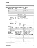
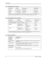
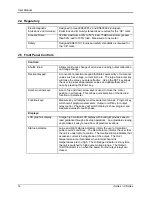
Страница 25: ...User Manual i Series iX Series 11 Parameter Specification Shock Designed to meet NSTA 1A transportation levels...
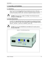
Страница 38: ...User Manual 24 i Series iX Series Figure 3 5 Rear Panel View for the 3001i 3001iX...
Страница 39: ...User Manual i Series iX Series 25 Figure 3 6 Rear Panel View for the 5001i 5001iX...
Страница 42: ...User Manual 28 i Series iX Series Figure 3 7 Connection For Single Power Source 5001iX i 3001iX i...
Страница 43: ...User Manual i Series iX Series 29 Figure 3 8 Functional Test Setup...
Страница 44: ...User Manual 30 i Series iX Series Figure 3 9 Single Phase 10000 VA System 10001iX i...
Страница 45: ...User Manual i Series iX Series 31 Figure 3 10 Three Phase 15000 VA System 15003iX i LK Three Controllers...
Страница 46: ...User Manual 32 i Series iX Series Figure 3 11 Single Phase 15000 VA System 15001iX i...
Страница 47: ...User Manual i Series iX Series 33 Figure 3 12 Three Phase 15000 VA system 15003iX i One Controller...
Страница 48: ...User Manual 34 i Series iX Series Figure 3 13 Connection With MODE Option...
Страница 49: ...User Manual i Series iX Series 35 Figure 3 14 Two Phase 10000 VA System 10002i LK Two Controllers...
Страница 50: ...User Manual 36 i Series iX Series Figure 3 15 Three Phase 9000 VA System 9003iX i One Controller...
Страница 118: ...User Manual 104 i Series iX Series Figure 5 2 Power Source Module Block Diagram...
Страница 121: ...User Manual i Series iX Series 107 Figure 5 3 5001i Internal Layout...
Страница 122: ...User Manual 108 i Series iX Series Figure 5 4 Logic Board LED s...
Страница 124: ...User Manual 110 i Series iX Series Figure 5 5 AC Power Stage Layout...
Страница 125: ...User Manual i Series iX Series 111 Figure 5 6 AC Control Logic Block Diagram...
Страница 132: ...User Manual 118 i Series iX Series Figure 6 2 Test Equipment Hook up for Measurement Calibration...
Страница 138: ...User Manual 124 i Series iX Series Figure 6 3 Adjustment Location...
Страница 152: ...User Manual 138 i Series iX Series Figure 9 4 Voltage Modulation...
Страница 219: ...User Manual i Series iX Series 205 Figure 9 36 Example Connection With 5001iX and EOS 1...
Страница 220: ...User Manual 206 i Series iX Series Figure 9 37 Example Connection With Compliance Test System and EOS 1...
Страница 221: ...User Manual i Series iX Series 207 Figure 9 38 15003iX CTS EOS3 LR3...
Страница 222: ...User Manual 208 i Series iX Series Figure 9 39 15003iX 3 EOS3...
Страница 226: ...User Manual 212 i Series iX Series Figure 9 40 EOS3 Location of 70 80 Taps for each phase Lug 3 70 Lug 5 80...
Страница 233: ...User Manual i Series iX Series 219 Figure 9 41 Example Connection With MODE iX...
Страница 240: ...User Manual 226 i Series iX Series Figure 9 42 Example Connections With OMNI 1 18i...
Страница 241: ...User Manual i Series iX Series 227 Figure 9 43 Example Connections With OMNI 3 18i...
Страница 242: ...User Manual 228 i Series iX Series Figure 9 44 Schematic Showing OMNI 1 37i and1 37iJ Connected to 5001iX System...
Страница 243: ...User Manual i Series iX Series 229 Figure 9 45 Schematic Showing OMNI 3 37i Connected to 30003iX System...
Страница 249: ...User Manual i Series iX Series 235 9 7 4 Mechanical Dimensions Figure 9 49 XLS Module Dimensions...