User Manual
122
i Series / iX Series
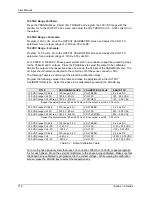
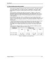
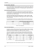
5. Calculate the resistive and inductive component R and L using the formulas shown in Table
6-8. (Alternatively, use the 16 bit CIGUI.)
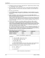
6. Enter these values, in the OUTPUT CAL screen for the IMP. REAL MIN and IMP. REACT
MIN value respectively. Make sure the correct phase is selected or use the PHASE key if
not.
7. Remove or turn off the load.
8. From the MENU 3 screen, select OUTPUT IMPEDANCE. Press the PHASE key to select
the phase to be calibrated. Program the output inductance to 796 uH and the resistance to
400 mOhms.
9. Select the Calibration, Output screen and move the cursor to the IMP REAL FS field.
Measure the R and L by removing and applying the load as described before and calculating
the R and L using the formula's in Table 6-7.
Adjust the resistive output impedance using the shuttle until the measured output is as close
as possible to 400 mOhm. Make sure the correct phase is selected or use the PHASE key if
not. Do the same with the IMP REACT FS field. Note that the adjustment range for R is 0 to
100, for L is 0 to 300.
10. If there is not enough range in the full-scale calibration coefficient for either resistive or
inductive portion, it may be necessary to tweak the adjustment pots on the iX controller.
These pots were originally adjusted at the factory and normally do not have to be adjusted
again. The Full Scale calibration coefficients should have enough adjustment range. Double
check the connections and phase measurements if this is not the case to make sure the
measurement readings you get are indeed correct.
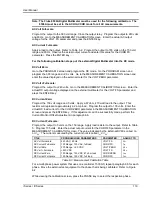
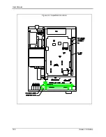
If it is necessary to adjust the pots, see Table 6-7 for the corresponding pot designators. The
top cover has to be removed to access these pots. They are located along the top edge of
the controller board(s). Adjustments for phase A are on the phase A/CPU board (5100-707),
adjustments for phase B and C are on the phase B/C board (7000-722).
11. Repeat steps 2 through 10 for phase B and C.
Phase / Board Assembly #
R resistive
Xl inductive
Phase A /CPU (5100-707)
R121
R122
Phase B (7000-722)
R112
R111
Phase C (7000-722)
R114
R115
Table 6-7: Programmable Z adjustment pots
Definitions:
V
NL
= Measured RMS voltage under no load.
V
L
= Measured RMS voltage under load
I = Measured RMS current.
F = Source frequency (50 Hz).
= Phase angle shift between load and no load conditions. Record phase angle
from phase meter under NL and L condition and determine phase shift.
Formulas to calculate R and L component of output impedance:
R = ( V
NL
* cos(
) - V
L
) / I
X
L
= ( V
NL
* sin(
)) / I
L = X
L
/ (2 * Pi * F)
Table 6-8: Formulas to calculate R and L
Содержание 10001i
Страница 2: ......
Страница 3: ......
Страница 6: ...ii This page intentionally left blank...
Страница 25: ...User Manual i Series iX Series 11 Parameter Specification Shock Designed to meet NSTA 1A transportation levels...
Страница 38: ...User Manual 24 i Series iX Series Figure 3 5 Rear Panel View for the 3001i 3001iX...
Страница 39: ...User Manual i Series iX Series 25 Figure 3 6 Rear Panel View for the 5001i 5001iX...
Страница 42: ...User Manual 28 i Series iX Series Figure 3 7 Connection For Single Power Source 5001iX i 3001iX i...
Страница 43: ...User Manual i Series iX Series 29 Figure 3 8 Functional Test Setup...
Страница 44: ...User Manual 30 i Series iX Series Figure 3 9 Single Phase 10000 VA System 10001iX i...
Страница 45: ...User Manual i Series iX Series 31 Figure 3 10 Three Phase 15000 VA System 15003iX i LK Three Controllers...
Страница 46: ...User Manual 32 i Series iX Series Figure 3 11 Single Phase 15000 VA System 15001iX i...
Страница 47: ...User Manual i Series iX Series 33 Figure 3 12 Three Phase 15000 VA system 15003iX i One Controller...
Страница 48: ...User Manual 34 i Series iX Series Figure 3 13 Connection With MODE Option...
Страница 49: ...User Manual i Series iX Series 35 Figure 3 14 Two Phase 10000 VA System 10002i LK Two Controllers...
Страница 50: ...User Manual 36 i Series iX Series Figure 3 15 Three Phase 9000 VA System 9003iX i One Controller...
Страница 118: ...User Manual 104 i Series iX Series Figure 5 2 Power Source Module Block Diagram...
Страница 121: ...User Manual i Series iX Series 107 Figure 5 3 5001i Internal Layout...
Страница 122: ...User Manual 108 i Series iX Series Figure 5 4 Logic Board LED s...
Страница 124: ...User Manual 110 i Series iX Series Figure 5 5 AC Power Stage Layout...
Страница 125: ...User Manual i Series iX Series 111 Figure 5 6 AC Control Logic Block Diagram...
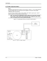
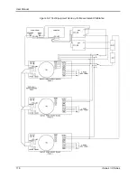
Страница 132: ...User Manual 118 i Series iX Series Figure 6 2 Test Equipment Hook up for Measurement Calibration...
Страница 138: ...User Manual 124 i Series iX Series Figure 6 3 Adjustment Location...
Страница 152: ...User Manual 138 i Series iX Series Figure 9 4 Voltage Modulation...
Страница 219: ...User Manual i Series iX Series 205 Figure 9 36 Example Connection With 5001iX and EOS 1...
Страница 220: ...User Manual 206 i Series iX Series Figure 9 37 Example Connection With Compliance Test System and EOS 1...
Страница 221: ...User Manual i Series iX Series 207 Figure 9 38 15003iX CTS EOS3 LR3...
Страница 222: ...User Manual 208 i Series iX Series Figure 9 39 15003iX 3 EOS3...
Страница 226: ...User Manual 212 i Series iX Series Figure 9 40 EOS3 Location of 70 80 Taps for each phase Lug 3 70 Lug 5 80...
Страница 233: ...User Manual i Series iX Series 219 Figure 9 41 Example Connection With MODE iX...
Страница 240: ...User Manual 226 i Series iX Series Figure 9 42 Example Connections With OMNI 1 18i...
Страница 241: ...User Manual i Series iX Series 227 Figure 9 43 Example Connections With OMNI 3 18i...
Страница 242: ...User Manual 228 i Series iX Series Figure 9 44 Schematic Showing OMNI 1 37i and1 37iJ Connected to 5001iX System...
Страница 243: ...User Manual i Series iX Series 229 Figure 9 45 Schematic Showing OMNI 3 37i Connected to 30003iX System...
Страница 249: ...User Manual i Series iX Series 235 9 7 4 Mechanical Dimensions Figure 9 49 XLS Module Dimensions...

