


User Manual
i Series / iX Series
211
9.4.6.4 EOS3 70/80 Tap setting change
Second generation EOS3 units are equipped with both a 70% and an 80% output tap. The
default EOS3 configuration shipped from the factor is set to the 70% tap. This is the most
commonly used dip level for product standards. However, Edition 2.0 of the IEC 61000-4-11 test
standard does allow for a 80% dip level for which the alternate tap setting may be used. If testing
for 80% dips is required, the EOS3 must be reconfigured. This can only be done by removing the
top cover and changing the connections on the three transformer taps inside the EOS3, one for
each phage. As such, this configuration change should be avoided as much as possible. Should
a configuration change be required, follow the procedure outlined below.
1. Remove all input power from the EOS3 first. Make sure the 15001iX is turned off. Then
disconnect the output of the 15003iX power source from the EOS input.
2. With the EOS3 completely disconnected, remove the top cover by removing the Phillips
screws of the top cover.
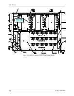
3. Each transformer
– one per phase – has five output tap lugs connected to a wire harness.
The wire harness routes the output of each tap the electronic switches on the control board.
There is one control board for each phase mounted to a heat sink.
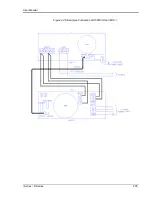
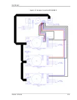
4. The output tap lugs are numbered 1, 2, 3, 5, 4 in that order on the transformer. The 70%
output tap is available on lug number 3. The 80% output tap is available on lug number 5. To
change taps, some hand tools (wrench, pliers) will be required.
To switch from 70% to 80% tap, disconnect the wire from lug 3 and reconnect it to lug 5
on each of the three transformers.
To switch from 80% to 70% tap, disconnect the wire from lug 5 and reconnect it to lug 3
on each of the three transformers.
5. Replace the top cover.
Although it is possible to wire each phase for a different tap level, this is not recommended. It
may be advisable to mark the unit to reflect the configured tap after making a configuration
change.
Содержание 10001i
Страница 2: ......
Страница 3: ......
Страница 6: ...ii This page intentionally left blank...
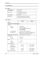
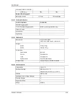
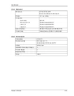
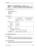
Страница 25: ...User Manual i Series iX Series 11 Parameter Specification Shock Designed to meet NSTA 1A transportation levels...
Страница 38: ...User Manual 24 i Series iX Series Figure 3 5 Rear Panel View for the 3001i 3001iX...
Страница 39: ...User Manual i Series iX Series 25 Figure 3 6 Rear Panel View for the 5001i 5001iX...
Страница 42: ...User Manual 28 i Series iX Series Figure 3 7 Connection For Single Power Source 5001iX i 3001iX i...
Страница 43: ...User Manual i Series iX Series 29 Figure 3 8 Functional Test Setup...
Страница 44: ...User Manual 30 i Series iX Series Figure 3 9 Single Phase 10000 VA System 10001iX i...
Страница 45: ...User Manual i Series iX Series 31 Figure 3 10 Three Phase 15000 VA System 15003iX i LK Three Controllers...
Страница 46: ...User Manual 32 i Series iX Series Figure 3 11 Single Phase 15000 VA System 15001iX i...
Страница 47: ...User Manual i Series iX Series 33 Figure 3 12 Three Phase 15000 VA system 15003iX i One Controller...
Страница 48: ...User Manual 34 i Series iX Series Figure 3 13 Connection With MODE Option...
Страница 49: ...User Manual i Series iX Series 35 Figure 3 14 Two Phase 10000 VA System 10002i LK Two Controllers...
Страница 50: ...User Manual 36 i Series iX Series Figure 3 15 Three Phase 9000 VA System 9003iX i One Controller...
Страница 118: ...User Manual 104 i Series iX Series Figure 5 2 Power Source Module Block Diagram...
Страница 121: ...User Manual i Series iX Series 107 Figure 5 3 5001i Internal Layout...
Страница 122: ...User Manual 108 i Series iX Series Figure 5 4 Logic Board LED s...
Страница 124: ...User Manual 110 i Series iX Series Figure 5 5 AC Power Stage Layout...
Страница 125: ...User Manual i Series iX Series 111 Figure 5 6 AC Control Logic Block Diagram...
Страница 132: ...User Manual 118 i Series iX Series Figure 6 2 Test Equipment Hook up for Measurement Calibration...
Страница 138: ...User Manual 124 i Series iX Series Figure 6 3 Adjustment Location...
Страница 152: ...User Manual 138 i Series iX Series Figure 9 4 Voltage Modulation...
Страница 219: ...User Manual i Series iX Series 205 Figure 9 36 Example Connection With 5001iX and EOS 1...
Страница 220: ...User Manual 206 i Series iX Series Figure 9 37 Example Connection With Compliance Test System and EOS 1...
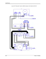
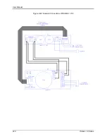
Страница 221: ...User Manual i Series iX Series 207 Figure 9 38 15003iX CTS EOS3 LR3...
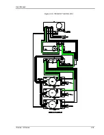
Страница 222: ...User Manual 208 i Series iX Series Figure 9 39 15003iX 3 EOS3...
Страница 226: ...User Manual 212 i Series iX Series Figure 9 40 EOS3 Location of 70 80 Taps for each phase Lug 3 70 Lug 5 80...
Страница 233: ...User Manual i Series iX Series 219 Figure 9 41 Example Connection With MODE iX...
Страница 240: ...User Manual 226 i Series iX Series Figure 9 42 Example Connections With OMNI 1 18i...
Страница 241: ...User Manual i Series iX Series 227 Figure 9 43 Example Connections With OMNI 3 18i...
Страница 242: ...User Manual 228 i Series iX Series Figure 9 44 Schematic Showing OMNI 1 37i and1 37iJ Connected to 5001iX System...
Страница 243: ...User Manual i Series iX Series 229 Figure 9 45 Schematic Showing OMNI 3 37i Connected to 30003iX System...
Страница 249: ...User Manual i Series iX Series 235 9 7 4 Mechanical Dimensions Figure 9 49 XLS Module Dimensions...