


User Manual
i Series / iX Series
19
J22
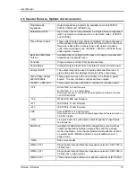
Description
sync input. It connects to the cathode of an LED at the input of an optocoupler. Refer to
J22-32.
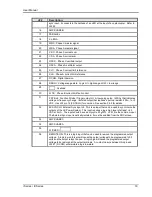
16
AMP SHARE B
17
PARALLEL
18
CL ENA
19
MR C: Phase C master signal
20
MR A: Phase A master signal
21
CS C: Phase C current sum
22
CS A: Phase A current sum
23
OSC C: Phase C oscillator output
24
OSC A: Phase A oscillator output
25
CL C: Phase C current limit reference
26
CL A: Phase A current limit reference
27
D COM: Digital Common
28
RNG HI: Voltage range state: Logic HI = high range, LOW = low range
29
: Overload
30
FLT B: Phase B current limit fault control
31
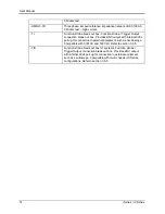
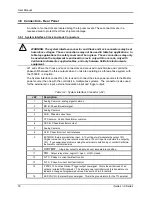
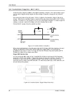
F STB HI: Function Strobe / Trigger output HI. A low-going pulse, >400 s, that indicates
voltage or frequency change. Isolated output that requires a pull-up resistor, 22K , to +5
VDC. Use J22 pin 14 (F STB LO) for common. See section 3.6.5 for details.
32
EX SYNC HI, External Sync input HI. This is an input that can be used to synchronize the
outputs of the AC Power System. This input requires a logic high level of at least +4.5
VDC at 5 mA. The input should have a duty cycle 50 30%. J22-15 is the common input.
The External Sync input is optically isolated. It must be enabled from the SNC screen.
33
AMP SHARE C
34
AMP SHARE A
35
FLICKER /
36
REMOTE ON: This is a logic input that can be used to remove the programmed output
voltage. A logic low on this pin will cause the output voltages to be programmed to 0.0
volts and the output relays to open. A logic high will cause the programmed output
voltage to be restored at the output terminals. A contact closure between this pin and
J22-27 (D COM) will simulate a logic low state.
Содержание 10001i
Страница 2: ......
Страница 3: ......
Страница 6: ...ii This page intentionally left blank...
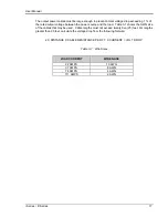
Страница 25: ...User Manual i Series iX Series 11 Parameter Specification Shock Designed to meet NSTA 1A transportation levels...
Страница 38: ...User Manual 24 i Series iX Series Figure 3 5 Rear Panel View for the 3001i 3001iX...
Страница 39: ...User Manual i Series iX Series 25 Figure 3 6 Rear Panel View for the 5001i 5001iX...
Страница 42: ...User Manual 28 i Series iX Series Figure 3 7 Connection For Single Power Source 5001iX i 3001iX i...
Страница 43: ...User Manual i Series iX Series 29 Figure 3 8 Functional Test Setup...
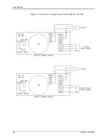
Страница 44: ...User Manual 30 i Series iX Series Figure 3 9 Single Phase 10000 VA System 10001iX i...
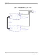
Страница 45: ...User Manual i Series iX Series 31 Figure 3 10 Three Phase 15000 VA System 15003iX i LK Three Controllers...
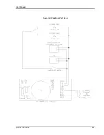
Страница 46: ...User Manual 32 i Series iX Series Figure 3 11 Single Phase 15000 VA System 15001iX i...
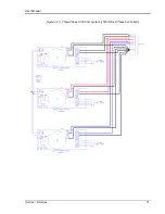
Страница 47: ...User Manual i Series iX Series 33 Figure 3 12 Three Phase 15000 VA system 15003iX i One Controller...
Страница 48: ...User Manual 34 i Series iX Series Figure 3 13 Connection With MODE Option...
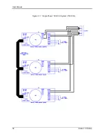
Страница 49: ...User Manual i Series iX Series 35 Figure 3 14 Two Phase 10000 VA System 10002i LK Two Controllers...
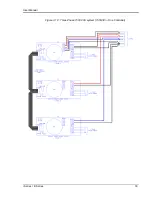
Страница 50: ...User Manual 36 i Series iX Series Figure 3 15 Three Phase 9000 VA System 9003iX i One Controller...
Страница 118: ...User Manual 104 i Series iX Series Figure 5 2 Power Source Module Block Diagram...
Страница 121: ...User Manual i Series iX Series 107 Figure 5 3 5001i Internal Layout...
Страница 122: ...User Manual 108 i Series iX Series Figure 5 4 Logic Board LED s...
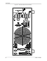
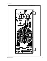
Страница 124: ...User Manual 110 i Series iX Series Figure 5 5 AC Power Stage Layout...
Страница 125: ...User Manual i Series iX Series 111 Figure 5 6 AC Control Logic Block Diagram...
Страница 132: ...User Manual 118 i Series iX Series Figure 6 2 Test Equipment Hook up for Measurement Calibration...
Страница 138: ...User Manual 124 i Series iX Series Figure 6 3 Adjustment Location...
Страница 152: ...User Manual 138 i Series iX Series Figure 9 4 Voltage Modulation...
Страница 219: ...User Manual i Series iX Series 205 Figure 9 36 Example Connection With 5001iX and EOS 1...
Страница 220: ...User Manual 206 i Series iX Series Figure 9 37 Example Connection With Compliance Test System and EOS 1...
Страница 221: ...User Manual i Series iX Series 207 Figure 9 38 15003iX CTS EOS3 LR3...
Страница 222: ...User Manual 208 i Series iX Series Figure 9 39 15003iX 3 EOS3...
Страница 226: ...User Manual 212 i Series iX Series Figure 9 40 EOS3 Location of 70 80 Taps for each phase Lug 3 70 Lug 5 80...
Страница 233: ...User Manual i Series iX Series 219 Figure 9 41 Example Connection With MODE iX...
Страница 240: ...User Manual 226 i Series iX Series Figure 9 42 Example Connections With OMNI 1 18i...
Страница 241: ...User Manual i Series iX Series 227 Figure 9 43 Example Connections With OMNI 3 18i...
Страница 242: ...User Manual 228 i Series iX Series Figure 9 44 Schematic Showing OMNI 1 37i and1 37iJ Connected to 5001iX System...
Страница 243: ...User Manual i Series iX Series 229 Figure 9 45 Schematic Showing OMNI 3 37i Connected to 30003iX System...
Страница 249: ...User Manual i Series iX Series 235 9 7 4 Mechanical Dimensions Figure 9 49 XLS Module Dimensions...