


User Manual
i Series / iX Series
155
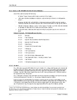
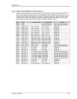
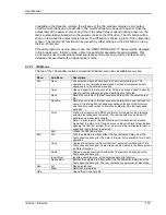
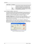
9.1.2.5 Initial Setup
The
–160 option supports both AC and DC modes of operation. The correct mode is a function of
the EUT to be tested and the operator must select the corresponding operating mode first. This
can be done from the front panel if needed or using the CIGui32 program. Use of the CIGui32
program for all settings will be assumed for the remainder of this chapter.
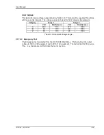
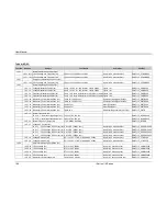
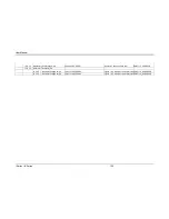
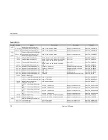
The following twelve power groups are covered in the RTCA/DO-160 directive:
Category reference:
-
For ac equipment: A(CF), A(NF), and A(WF)
-
For dc equipment: A, B, Z
-
AC tests can be performed at 115V nominal or 230V nominal, except A(NF) and
A(CF) which can only be done at 115V nominal. All AC line voltage shown are L-N.
-
DC tests can be performed at 28V nominal or 14V nominal
Definitions:
A(CF):
designates ac equipment intended for use on aircraft electrical systems where the
primary power is from constant frequency (400 Hz) ac system.
A(NF):
designates ac equipment intended for use on aircraft electrical systems where the
primary power is from narrow variable frequency (360 to 650 Hz) ac system.
A(WF):
designates ac equipment intended for use on aircraft electrical systems where the
primary power is from wide variable frequency (360 to 800 Hz) ac system.
A:
designates dc equipment intended for use on aircraft electrical systems where the dc is
generated from primary power supplied from either a constant or variable frequency ac system.
B:
designates dc equipment intended for use on aircraft electrical systems supplied by engine-
driven alternator/rectifiers, or dc generators where a battery of significant capacity is floating on
the dc bus at all times.
Z:
designates dc equipment that may be used on all other types of aircraft electrical systems
applicable to these standards. Category Z shall be acceptable for use in lieu of Category A or
Category B.
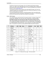
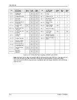
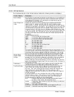
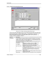
The required steady state output settings for each power group must be selected based on the
type of EUT to be tested. These settings can be made from the front panel of the iX Series power
source or from the main CIGui32 control screen.
Содержание 10001i
Страница 2: ......
Страница 3: ......
Страница 6: ...ii This page intentionally left blank...
Страница 25: ...User Manual i Series iX Series 11 Parameter Specification Shock Designed to meet NSTA 1A transportation levels...
Страница 38: ...User Manual 24 i Series iX Series Figure 3 5 Rear Panel View for the 3001i 3001iX...
Страница 39: ...User Manual i Series iX Series 25 Figure 3 6 Rear Panel View for the 5001i 5001iX...
Страница 42: ...User Manual 28 i Series iX Series Figure 3 7 Connection For Single Power Source 5001iX i 3001iX i...
Страница 43: ...User Manual i Series iX Series 29 Figure 3 8 Functional Test Setup...
Страница 44: ...User Manual 30 i Series iX Series Figure 3 9 Single Phase 10000 VA System 10001iX i...
Страница 45: ...User Manual i Series iX Series 31 Figure 3 10 Three Phase 15000 VA System 15003iX i LK Three Controllers...
Страница 46: ...User Manual 32 i Series iX Series Figure 3 11 Single Phase 15000 VA System 15001iX i...
Страница 47: ...User Manual i Series iX Series 33 Figure 3 12 Three Phase 15000 VA system 15003iX i One Controller...
Страница 48: ...User Manual 34 i Series iX Series Figure 3 13 Connection With MODE Option...
Страница 49: ...User Manual i Series iX Series 35 Figure 3 14 Two Phase 10000 VA System 10002i LK Two Controllers...
Страница 50: ...User Manual 36 i Series iX Series Figure 3 15 Three Phase 9000 VA System 9003iX i One Controller...
Страница 118: ...User Manual 104 i Series iX Series Figure 5 2 Power Source Module Block Diagram...
Страница 121: ...User Manual i Series iX Series 107 Figure 5 3 5001i Internal Layout...
Страница 122: ...User Manual 108 i Series iX Series Figure 5 4 Logic Board LED s...
Страница 124: ...User Manual 110 i Series iX Series Figure 5 5 AC Power Stage Layout...
Страница 125: ...User Manual i Series iX Series 111 Figure 5 6 AC Control Logic Block Diagram...
Страница 132: ...User Manual 118 i Series iX Series Figure 6 2 Test Equipment Hook up for Measurement Calibration...
Страница 138: ...User Manual 124 i Series iX Series Figure 6 3 Adjustment Location...
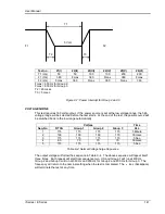
Страница 152: ...User Manual 138 i Series iX Series Figure 9 4 Voltage Modulation...
Страница 219: ...User Manual i Series iX Series 205 Figure 9 36 Example Connection With 5001iX and EOS 1...
Страница 220: ...User Manual 206 i Series iX Series Figure 9 37 Example Connection With Compliance Test System and EOS 1...
Страница 221: ...User Manual i Series iX Series 207 Figure 9 38 15003iX CTS EOS3 LR3...
Страница 222: ...User Manual 208 i Series iX Series Figure 9 39 15003iX 3 EOS3...
Страница 226: ...User Manual 212 i Series iX Series Figure 9 40 EOS3 Location of 70 80 Taps for each phase Lug 3 70 Lug 5 80...
Страница 233: ...User Manual i Series iX Series 219 Figure 9 41 Example Connection With MODE iX...
Страница 240: ...User Manual 226 i Series iX Series Figure 9 42 Example Connections With OMNI 1 18i...
Страница 241: ...User Manual i Series iX Series 227 Figure 9 43 Example Connections With OMNI 3 18i...
Страница 242: ...User Manual 228 i Series iX Series Figure 9 44 Schematic Showing OMNI 1 37i and1 37iJ Connected to 5001iX System...
Страница 243: ...User Manual i Series iX Series 229 Figure 9 45 Schematic Showing OMNI 3 37i Connected to 30003iX System...
Страница 249: ...User Manual i Series iX Series 235 9 7 4 Mechanical Dimensions Figure 9 49 XLS Module Dimensions...