User Manual
128
i Series / iX Series
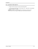
7.4.4 Fuse Check
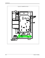
See Figure 5-3 and Figure 5-5. Check the fuse F1 on the AC power board at the top of the unit
using the ohmmeter. If the fuse is open do not replace but check all the IGBT‟s. To check the
IGBT‟s connect the positive lead of the ohmmeter to the collector (center leg) and measure the
resistance to the gate and the emitter (outside legs) of each IGBT. If the resistance reading is
lower than 1000 ohms it indicates a blown IGBT. The IGBT‟s are not field replaceable and the
module should be returned to the factory for exchange or repair. See paragraph 7.4.6.
for
disassembly instructions. If a low resistance reading is not found, replace the fuse and proceed
with the check procedure.
Check the fuse F1 on the end of the input/output board. If the fuse is blown do not replace but
proceed to paragraph 7.4.6 for disassembly instructions and remove the AC power board. With
the AC power board removed check the IGBT‟s Q2 through Q9 using the procedure detailed in
the paragraph above. See Figure 6-1: Internal Top View of DC-DC Converter Board.
If one or more IGBT‟s show a low resistance reading do not replace the fuse but return the
module to the factory for exchange or repair. If a low resistance is not found, replace the fuse
and carry on with the check procedure.
7.4.5 Power-on Tro
ubleshooting Using the LED’s.
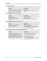
If no fuses were blown or if fuses were found blown but all the IGBT‟s checked out as good,
replace blown fuses and reconnect power to the unit.
WARNING:
Do not touch any parts inside the unit during this test as they will
be live and dangerous. Always wear safety glasses.
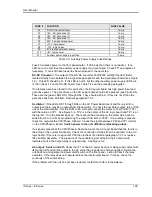
Auxiliary PS:
Turn the main breaker on and check the LED‟s on the AC logic board.(see Figure
5-4). The +15V (DS2-red), -15V (DS3-green), and the 24V (DS7-
amber) LED‟s located at the
top right of the board should all be lit. The 8V logic supply LED (DS4- red) should be lit. On the
AC power board (see Figure 5-5) the three gate drive power supply lights, DS5-green, DS6-
amber, and DS7-
red, should all be lit. If any of these LED‟s are not lit then the most likely cause
is a blown fuse. These logic power fuses are all located on the DC-DC board. Switch the unit off
at the front panel breaker
and
remove the input power.
Wait 10 minutes to allow the capacitors to discharge
before attempting to disassemble the unit.
Proceed to paragraph 7.4.6.
for disassembly instructions. Remove the AC power board and
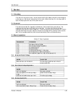
locate the P.C. mount fuses F2 through F10 (see Table 7-2 for fuse functions). Replace any
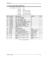
blown fuses. Always replace fuses with same type and rating. (See Table 8-2.)
Содержание 10001i
Страница 2: ......
Страница 3: ......
Страница 6: ...ii This page intentionally left blank...
Страница 25: ...User Manual i Series iX Series 11 Parameter Specification Shock Designed to meet NSTA 1A transportation levels...
Страница 38: ...User Manual 24 i Series iX Series Figure 3 5 Rear Panel View for the 3001i 3001iX...
Страница 39: ...User Manual i Series iX Series 25 Figure 3 6 Rear Panel View for the 5001i 5001iX...
Страница 42: ...User Manual 28 i Series iX Series Figure 3 7 Connection For Single Power Source 5001iX i 3001iX i...
Страница 43: ...User Manual i Series iX Series 29 Figure 3 8 Functional Test Setup...
Страница 44: ...User Manual 30 i Series iX Series Figure 3 9 Single Phase 10000 VA System 10001iX i...
Страница 45: ...User Manual i Series iX Series 31 Figure 3 10 Three Phase 15000 VA System 15003iX i LK Three Controllers...
Страница 46: ...User Manual 32 i Series iX Series Figure 3 11 Single Phase 15000 VA System 15001iX i...
Страница 47: ...User Manual i Series iX Series 33 Figure 3 12 Three Phase 15000 VA system 15003iX i One Controller...
Страница 48: ...User Manual 34 i Series iX Series Figure 3 13 Connection With MODE Option...
Страница 49: ...User Manual i Series iX Series 35 Figure 3 14 Two Phase 10000 VA System 10002i LK Two Controllers...
Страница 50: ...User Manual 36 i Series iX Series Figure 3 15 Three Phase 9000 VA System 9003iX i One Controller...
Страница 118: ...User Manual 104 i Series iX Series Figure 5 2 Power Source Module Block Diagram...
Страница 121: ...User Manual i Series iX Series 107 Figure 5 3 5001i Internal Layout...
Страница 122: ...User Manual 108 i Series iX Series Figure 5 4 Logic Board LED s...
Страница 124: ...User Manual 110 i Series iX Series Figure 5 5 AC Power Stage Layout...
Страница 125: ...User Manual i Series iX Series 111 Figure 5 6 AC Control Logic Block Diagram...
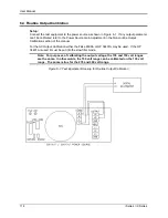
Страница 132: ...User Manual 118 i Series iX Series Figure 6 2 Test Equipment Hook up for Measurement Calibration...
Страница 138: ...User Manual 124 i Series iX Series Figure 6 3 Adjustment Location...
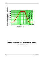
Страница 152: ...User Manual 138 i Series iX Series Figure 9 4 Voltage Modulation...
Страница 219: ...User Manual i Series iX Series 205 Figure 9 36 Example Connection With 5001iX and EOS 1...
Страница 220: ...User Manual 206 i Series iX Series Figure 9 37 Example Connection With Compliance Test System and EOS 1...
Страница 221: ...User Manual i Series iX Series 207 Figure 9 38 15003iX CTS EOS3 LR3...
Страница 222: ...User Manual 208 i Series iX Series Figure 9 39 15003iX 3 EOS3...
Страница 226: ...User Manual 212 i Series iX Series Figure 9 40 EOS3 Location of 70 80 Taps for each phase Lug 3 70 Lug 5 80...
Страница 233: ...User Manual i Series iX Series 219 Figure 9 41 Example Connection With MODE iX...
Страница 240: ...User Manual 226 i Series iX Series Figure 9 42 Example Connections With OMNI 1 18i...
Страница 241: ...User Manual i Series iX Series 227 Figure 9 43 Example Connections With OMNI 3 18i...
Страница 242: ...User Manual 228 i Series iX Series Figure 9 44 Schematic Showing OMNI 1 37i and1 37iJ Connected to 5001iX System...
Страница 243: ...User Manual i Series iX Series 229 Figure 9 45 Schematic Showing OMNI 3 37i Connected to 30003iX System...
Страница 249: ...User Manual i Series iX Series 235 9 7 4 Mechanical Dimensions Figure 9 49 XLS Module Dimensions...

