


User Manual
162
i Series / iX Series
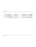
Control / Display
Description
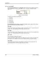
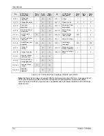
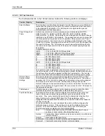
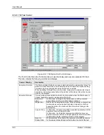
function is required to implement complex transients that require
multiple steps with zero time skew. When set to a value other
than blank or “0”, subsequent rows are considered part of the
same test step for single step or loop on step execution modes.
PhsB
Phase angle of phase B, only visible if phase angle is changed.
PhsC
Phase angle of phase C, only visible if phase angle is changed.
Comment
A comment about the specific test step.
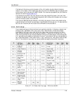
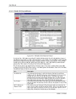
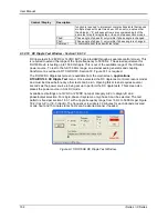
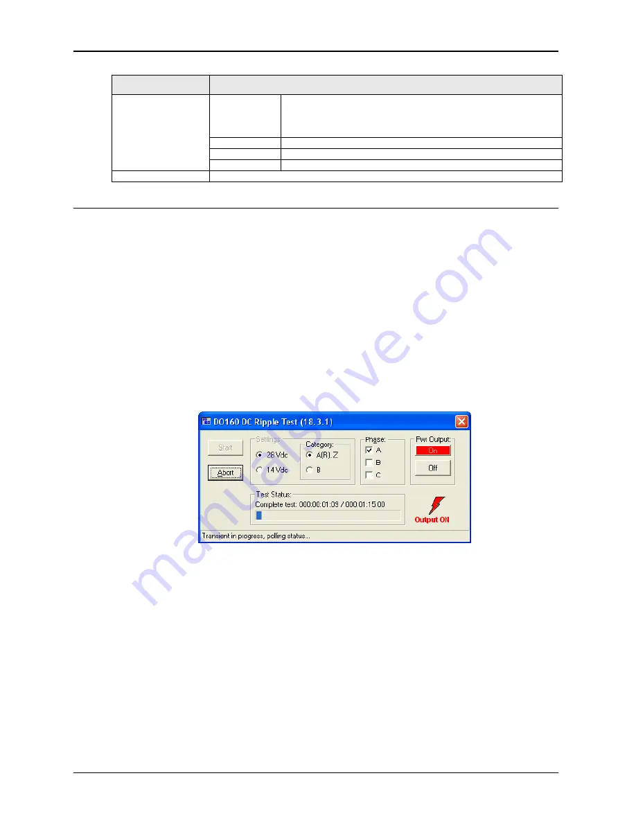
9.1.2.10 DC Ripple Test Window - Section 16.6.1.2
DC ripple tests f
or 28VDC or 14VDC EUT‟s are provided through a separate control screen. This
is required to extend the range of the ripple frequency to 5000 Hz. The actual requirement for
DO160 Rev E is testing up to 150 KHz ripple. This is out of the available range of the iX Series
power source. To test to the full 150 KHz range, an external audio generator and coupling
transformer as outlined in RTCA/DO160, Section 18, Figure 18-1 is required.
The DO160 DC Ripple test screen is available from the main screen,
Applications
,
RTCA/DO160
,
DC Ripple Test
menu. Once selected, the DC ripple test control screen is modal
and must be closed before any other tests can be run. Opening this screens requires several
seconds as the power source is being set up to perform the DC ripple tests. This screen also
places the power source in AC+DC mode.
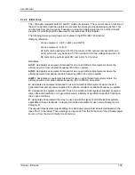
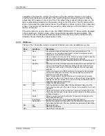
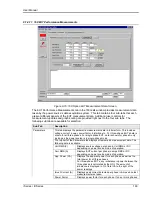
Available test settings are 14VDC or 28VDC nominal, category A,Z or category B and
phase/output selection. For single-phase iX systems, only phase A can be selected. The test
pattern is fixed per section 18.3.1 with a ripple frequency range from 16 Hz to 5000 Hz per Figure
18-2 (Cat A,Z) or 18-3 (Cat B). The frequency slew rate is 30 minutes for each decade covered
or one hour and 15 minutes total. Tests can be aborted sooner if needed.
Figure 9-15: DO160E DC Ripple Test Window.
Содержание 10001i
Страница 2: ......
Страница 3: ......
Страница 6: ...ii This page intentionally left blank...
Страница 25: ...User Manual i Series iX Series 11 Parameter Specification Shock Designed to meet NSTA 1A transportation levels...
Страница 38: ...User Manual 24 i Series iX Series Figure 3 5 Rear Panel View for the 3001i 3001iX...
Страница 39: ...User Manual i Series iX Series 25 Figure 3 6 Rear Panel View for the 5001i 5001iX...
Страница 42: ...User Manual 28 i Series iX Series Figure 3 7 Connection For Single Power Source 5001iX i 3001iX i...
Страница 43: ...User Manual i Series iX Series 29 Figure 3 8 Functional Test Setup...
Страница 44: ...User Manual 30 i Series iX Series Figure 3 9 Single Phase 10000 VA System 10001iX i...
Страница 45: ...User Manual i Series iX Series 31 Figure 3 10 Three Phase 15000 VA System 15003iX i LK Three Controllers...
Страница 46: ...User Manual 32 i Series iX Series Figure 3 11 Single Phase 15000 VA System 15001iX i...
Страница 47: ...User Manual i Series iX Series 33 Figure 3 12 Three Phase 15000 VA system 15003iX i One Controller...
Страница 48: ...User Manual 34 i Series iX Series Figure 3 13 Connection With MODE Option...
Страница 49: ...User Manual i Series iX Series 35 Figure 3 14 Two Phase 10000 VA System 10002i LK Two Controllers...
Страница 50: ...User Manual 36 i Series iX Series Figure 3 15 Three Phase 9000 VA System 9003iX i One Controller...
Страница 118: ...User Manual 104 i Series iX Series Figure 5 2 Power Source Module Block Diagram...
Страница 121: ...User Manual i Series iX Series 107 Figure 5 3 5001i Internal Layout...
Страница 122: ...User Manual 108 i Series iX Series Figure 5 4 Logic Board LED s...
Страница 124: ...User Manual 110 i Series iX Series Figure 5 5 AC Power Stage Layout...
Страница 125: ...User Manual i Series iX Series 111 Figure 5 6 AC Control Logic Block Diagram...
Страница 132: ...User Manual 118 i Series iX Series Figure 6 2 Test Equipment Hook up for Measurement Calibration...
Страница 138: ...User Manual 124 i Series iX Series Figure 6 3 Adjustment Location...
Страница 152: ...User Manual 138 i Series iX Series Figure 9 4 Voltage Modulation...
Страница 219: ...User Manual i Series iX Series 205 Figure 9 36 Example Connection With 5001iX and EOS 1...
Страница 220: ...User Manual 206 i Series iX Series Figure 9 37 Example Connection With Compliance Test System and EOS 1...
Страница 221: ...User Manual i Series iX Series 207 Figure 9 38 15003iX CTS EOS3 LR3...
Страница 222: ...User Manual 208 i Series iX Series Figure 9 39 15003iX 3 EOS3...
Страница 226: ...User Manual 212 i Series iX Series Figure 9 40 EOS3 Location of 70 80 Taps for each phase Lug 3 70 Lug 5 80...
Страница 233: ...User Manual i Series iX Series 219 Figure 9 41 Example Connection With MODE iX...
Страница 240: ...User Manual 226 i Series iX Series Figure 9 42 Example Connections With OMNI 1 18i...
Страница 241: ...User Manual i Series iX Series 227 Figure 9 43 Example Connections With OMNI 3 18i...
Страница 242: ...User Manual 228 i Series iX Series Figure 9 44 Schematic Showing OMNI 1 37i and1 37iJ Connected to 5001iX System...
Страница 243: ...User Manual i Series iX Series 229 Figure 9 45 Schematic Showing OMNI 3 37i Connected to 30003iX System...
Страница 249: ...User Manual i Series iX Series 235 9 7 4 Mechanical Dimensions Figure 9 49 XLS Module Dimensions...