User Manual
i Series / iX Series
129
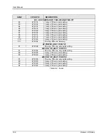
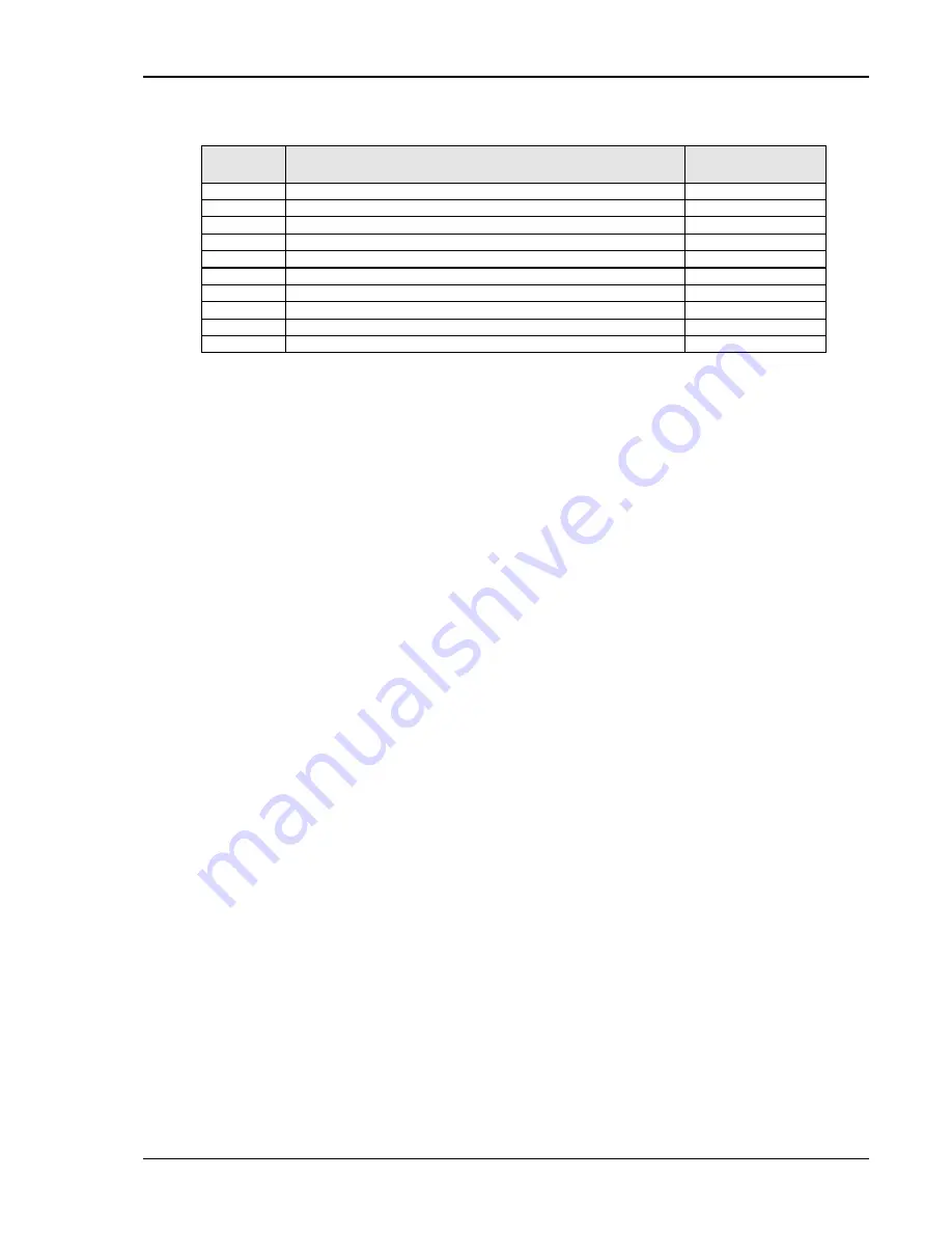
FUSE #
FUNCTION
FUSE VALUE
F2
DC-DC Converter logic
1 amp
F3
18V - AC gate drive (2)
1 amp
F4
18V - AC gate drive (3)
1 amp
F5
18V - AC gate drive (1)
1 amp
F6
24V Fan and relay power.
3 amp
F7
+15V logic power
1 amp
F8
-15V logic power
1 amp
F9
8V Front panel meter power
1 amp
F10
+8V logic power
3 amp
F11
Auxiliary power supply input fuse.
10 amp
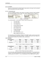
Table 7-2: Auxiliary Power Supply Fuse Ratings
Fuse F9 supplies power to the front panel meter. If F9 blows then there is no readout. If no
LED‟s are on at all, then the auxiliary power supply may have failed. Check F11 and replace if
necessary. If none of these fuses has blown proceed to the next step.
DC-DC Converter:
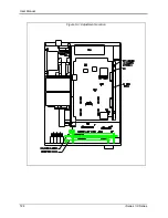
The output of the DC-DC converter 250V/500V will light the LED that is
located directly down between the large storage capacitor and the input/output board (see Figure
5-3). This LED should be lit. If this LED is not lit,
but the other auxiliary power supply LED‟s are
lit, then check F2 on the DC-DC board. See Table 7-2 and the preceding paragraph.
If no failures have been found to this point, then the AC power board has high power input and
gate drive power. The gate drives on the AC power board should all be present (see Figure 5-5).
These are the green LED‟s DS1 through DS4. They should all be lit. If they are not lit then the
gate drive has been inhibited. Recheck paragraph 7.3.7.
Oscillator:
If the LED‟s DS1 through DS4 on the AC Power Board are lit and there is still no
output then there may be no output from the oscillator. To check the oscillator output, turn off the
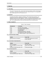
unit at the main breaker. Set the DVM to AC volts and connect the meter to Test Point 2 (TP2)
with the return on TP1. See Figure 5-4. TP2 is in the center of the AC logic board and TP1 is at
the top left. Turn the breaker back on. There should be a reading on the meter which can be
varied from 0 to 5 volts by programming the output from zero to 300V. If no reading is present,
check the output at the CPU/Phase A Board. Check the signal between TP29 and TP1 (return)
on the CPU/Phase A Board.
Switch power to the unit off before relocating probes.
If a signal is present at the CPU/Phase A Board but not at the AC Logic Board then the fault is in
the wiring or the current limit board. Check the continuity of cables from the oscillator to the AC
logic board. If there is no signal at TP29 then recheck the inhibit at paragraph 7.3.7 or replace
the oscillator assembly. The presence of the oscillator signal at the AC logic board would
indicate a fault in the output relay or output wiring. See Figure 5-2.
AC output: Switch unit off -
Check that P1 on the AC power board is making good contact with
its mating half and J8 (the output to the AC smoothing inductors) is firmly engaged. Switch the
unit back on and operate the power on/off switch on the front panel. Listen to hear if the relay
operates. If the relay does not operate replace the input/output board. If it does, check the
continuity of the output wiring.
If the problem with the unit has not been isolated, contact the factory for assistance.
Содержание 10001i
Страница 2: ......
Страница 3: ......
Страница 6: ...ii This page intentionally left blank...
Страница 25: ...User Manual i Series iX Series 11 Parameter Specification Shock Designed to meet NSTA 1A transportation levels...
Страница 38: ...User Manual 24 i Series iX Series Figure 3 5 Rear Panel View for the 3001i 3001iX...
Страница 39: ...User Manual i Series iX Series 25 Figure 3 6 Rear Panel View for the 5001i 5001iX...
Страница 42: ...User Manual 28 i Series iX Series Figure 3 7 Connection For Single Power Source 5001iX i 3001iX i...
Страница 43: ...User Manual i Series iX Series 29 Figure 3 8 Functional Test Setup...
Страница 44: ...User Manual 30 i Series iX Series Figure 3 9 Single Phase 10000 VA System 10001iX i...
Страница 45: ...User Manual i Series iX Series 31 Figure 3 10 Three Phase 15000 VA System 15003iX i LK Three Controllers...
Страница 46: ...User Manual 32 i Series iX Series Figure 3 11 Single Phase 15000 VA System 15001iX i...
Страница 47: ...User Manual i Series iX Series 33 Figure 3 12 Three Phase 15000 VA system 15003iX i One Controller...
Страница 48: ...User Manual 34 i Series iX Series Figure 3 13 Connection With MODE Option...
Страница 49: ...User Manual i Series iX Series 35 Figure 3 14 Two Phase 10000 VA System 10002i LK Two Controllers...
Страница 50: ...User Manual 36 i Series iX Series Figure 3 15 Three Phase 9000 VA System 9003iX i One Controller...
Страница 118: ...User Manual 104 i Series iX Series Figure 5 2 Power Source Module Block Diagram...
Страница 121: ...User Manual i Series iX Series 107 Figure 5 3 5001i Internal Layout...
Страница 122: ...User Manual 108 i Series iX Series Figure 5 4 Logic Board LED s...
Страница 124: ...User Manual 110 i Series iX Series Figure 5 5 AC Power Stage Layout...
Страница 125: ...User Manual i Series iX Series 111 Figure 5 6 AC Control Logic Block Diagram...
Страница 132: ...User Manual 118 i Series iX Series Figure 6 2 Test Equipment Hook up for Measurement Calibration...
Страница 138: ...User Manual 124 i Series iX Series Figure 6 3 Adjustment Location...
Страница 152: ...User Manual 138 i Series iX Series Figure 9 4 Voltage Modulation...
Страница 219: ...User Manual i Series iX Series 205 Figure 9 36 Example Connection With 5001iX and EOS 1...
Страница 220: ...User Manual 206 i Series iX Series Figure 9 37 Example Connection With Compliance Test System and EOS 1...
Страница 221: ...User Manual i Series iX Series 207 Figure 9 38 15003iX CTS EOS3 LR3...
Страница 222: ...User Manual 208 i Series iX Series Figure 9 39 15003iX 3 EOS3...
Страница 226: ...User Manual 212 i Series iX Series Figure 9 40 EOS3 Location of 70 80 Taps for each phase Lug 3 70 Lug 5 80...
Страница 233: ...User Manual i Series iX Series 219 Figure 9 41 Example Connection With MODE iX...
Страница 240: ...User Manual 226 i Series iX Series Figure 9 42 Example Connections With OMNI 1 18i...
Страница 241: ...User Manual i Series iX Series 227 Figure 9 43 Example Connections With OMNI 3 18i...
Страница 242: ...User Manual 228 i Series iX Series Figure 9 44 Schematic Showing OMNI 1 37i and1 37iJ Connected to 5001iX System...
Страница 243: ...User Manual i Series iX Series 229 Figure 9 45 Schematic Showing OMNI 3 37i Connected to 30003iX System...
Страница 249: ...User Manual i Series iX Series 235 9 7 4 Mechanical Dimensions Figure 9 49 XLS Module Dimensions...

