


User Manual
i Series / iX Series
259
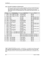
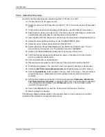
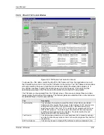
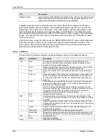
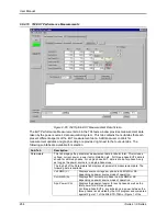
9.8.2.8 704 Test Selection
The Test Selections tab in the 704 test window contains the following controls and displays.
Control / Display
Description
Select Airframe.
This drop down control allows the operator to select from one or more libraries of
test sequences grouped by airframe. This allows multiple sets of test sequences
to be organized by application. The GUI program is supplied with a generic
MS704_RevX set of test sequences, where „X‟ is the rev of the standard being
tested to, which conform to the MIL-STD-704 document.
Power Group Test
Table
A library can contain up to seven power group test tables labeled SAC, TAC,
SVF, TVF, SXF, LDC, or HDC. These table names correspond to the Power
Groups identified in the MIL-STD-704 standard. Note that groups SAC, TAC,
SVF, TVF, and SXF are AC powered where as groups LDC and HDC are DC
powered. The operator cannot select a group that is not supported by the
present mode of operation of the power source. Thus, if the power source is in
AC mode, an error message will be display when trying to select group D or E.
Operating modes such as AC or DC must be changed from the main GUI screen.
The 704 screen can remain open while switching back to the main screen. Upon
return to the 704 screen, the relevant power groups can be selected.
Available power groups are:
Table SAC
Single Phase 115V / 400 Hz (CF) AC Power tests.
Table TAC
Three Phase 115V / 400 Hz (CF) AC Power tests.
Table SVF
Single Phase 115V / 360 to 800 Hz (VF) AC Power tests.
Table TVF
Three Phase 115V / 360 to 800 Hz (VF) AC Power tests.
Table SXF
Single Phase 115V / 60 Hz (CF) AC Power tests.
Table LDC
28 VDC Power tests.
Table HDC
270 VDC Power tests.
The operator needs to determine what the relevant power group selection is for
the unit under test. (EUT). When switching power groups, the table data shown at
the bottom of this tab will be updated to reflect the new selection. The first test
section of the table will automatically be selected when switching power groups.
Present Power
Source Output
Settings
This section displays the programmed steady state settings that are in effect.
This information is updated each time the 704 form regains focus. The mode of
operation (AC, DC or AC+DC) is displayed for reference but cannot be changed
from this screen. When in DC mode, the frequency setting will show “DC”.
Note that changes in steady state settings can only be made from the main GUI
screen. The operator can toggle between the main screen and the 704 screen for
this purpose as needed.
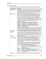
Table Header
The table header is shown against a blue background and contains the table
reference designator and a description of the selected power group.
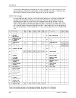
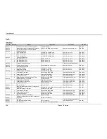
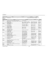
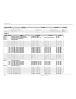
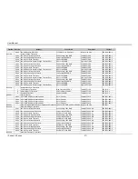
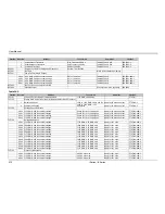
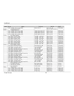
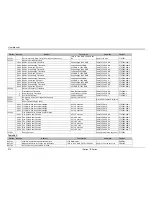
Test Table Display
The data grid at the bottom of the tab displays the selected power group test
table. It is also used to select the specific test section and number to be
executed. Thus, every test starts by selecting the desired test step from this
table. Clicking on the desired ROW does this. The selected row will be
highlighted and the associated file shown in the File Ref. Field will be loaded in
the Test Control tab.
For better readability, the user can adjust the column widths by dragging the
dividers between columns. If the window is too small to display all rows and
columns, scroll bars will appear at the bottom and/or right of the data grid.
The following fields are displayed in the test data tables.
Test
Number of the test from the MIL-STD-704 standard. For sub
sections of a test number, this field will be blank.
Section
Test section. Some tests may only have one section in which case
this field is blank.
Subject
Description of the type of test.
Test Limits
A summary of the test limits that will be applied by this test.
Comment
Comments concerning this test or its parameters.
File
Reference
The test sequence file that is used to implement this test section
on the power source.
User Data
The area at the bottom of this tab may be used to enter general information
Содержание 10001i
Страница 2: ......
Страница 3: ......
Страница 6: ...ii This page intentionally left blank...
Страница 25: ...User Manual i Series iX Series 11 Parameter Specification Shock Designed to meet NSTA 1A transportation levels...
Страница 38: ...User Manual 24 i Series iX Series Figure 3 5 Rear Panel View for the 3001i 3001iX...
Страница 39: ...User Manual i Series iX Series 25 Figure 3 6 Rear Panel View for the 5001i 5001iX...
Страница 42: ...User Manual 28 i Series iX Series Figure 3 7 Connection For Single Power Source 5001iX i 3001iX i...
Страница 43: ...User Manual i Series iX Series 29 Figure 3 8 Functional Test Setup...
Страница 44: ...User Manual 30 i Series iX Series Figure 3 9 Single Phase 10000 VA System 10001iX i...
Страница 45: ...User Manual i Series iX Series 31 Figure 3 10 Three Phase 15000 VA System 15003iX i LK Three Controllers...
Страница 46: ...User Manual 32 i Series iX Series Figure 3 11 Single Phase 15000 VA System 15001iX i...
Страница 47: ...User Manual i Series iX Series 33 Figure 3 12 Three Phase 15000 VA system 15003iX i One Controller...
Страница 48: ...User Manual 34 i Series iX Series Figure 3 13 Connection With MODE Option...
Страница 49: ...User Manual i Series iX Series 35 Figure 3 14 Two Phase 10000 VA System 10002i LK Two Controllers...
Страница 50: ...User Manual 36 i Series iX Series Figure 3 15 Three Phase 9000 VA System 9003iX i One Controller...
Страница 118: ...User Manual 104 i Series iX Series Figure 5 2 Power Source Module Block Diagram...
Страница 121: ...User Manual i Series iX Series 107 Figure 5 3 5001i Internal Layout...
Страница 122: ...User Manual 108 i Series iX Series Figure 5 4 Logic Board LED s...
Страница 124: ...User Manual 110 i Series iX Series Figure 5 5 AC Power Stage Layout...
Страница 125: ...User Manual i Series iX Series 111 Figure 5 6 AC Control Logic Block Diagram...
Страница 132: ...User Manual 118 i Series iX Series Figure 6 2 Test Equipment Hook up for Measurement Calibration...
Страница 138: ...User Manual 124 i Series iX Series Figure 6 3 Adjustment Location...
Страница 152: ...User Manual 138 i Series iX Series Figure 9 4 Voltage Modulation...
Страница 219: ...User Manual i Series iX Series 205 Figure 9 36 Example Connection With 5001iX and EOS 1...
Страница 220: ...User Manual 206 i Series iX Series Figure 9 37 Example Connection With Compliance Test System and EOS 1...
Страница 221: ...User Manual i Series iX Series 207 Figure 9 38 15003iX CTS EOS3 LR3...
Страница 222: ...User Manual 208 i Series iX Series Figure 9 39 15003iX 3 EOS3...
Страница 226: ...User Manual 212 i Series iX Series Figure 9 40 EOS3 Location of 70 80 Taps for each phase Lug 3 70 Lug 5 80...
Страница 233: ...User Manual i Series iX Series 219 Figure 9 41 Example Connection With MODE iX...
Страница 240: ...User Manual 226 i Series iX Series Figure 9 42 Example Connections With OMNI 1 18i...
Страница 241: ...User Manual i Series iX Series 227 Figure 9 43 Example Connections With OMNI 3 18i...
Страница 242: ...User Manual 228 i Series iX Series Figure 9 44 Schematic Showing OMNI 1 37i and1 37iJ Connected to 5001iX System...
Страница 243: ...User Manual i Series iX Series 229 Figure 9 45 Schematic Showing OMNI 3 37i Connected to 30003iX System...
Страница 249: ...User Manual i Series iX Series 235 9 7 4 Mechanical Dimensions Figure 9 49 XLS Module Dimensions...