


User Manual
i Series / iX Series
109
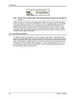
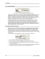
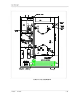
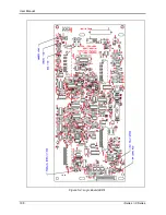
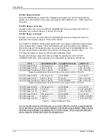
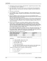
There are six LED indicators on the logic board. Their positions are shown in Figure 5-4. The
LED functions are listed in Table 5-1.
Table 5-1
: Logic Board LED’s
LED#
FUNCTION
COMMENTS
DS2
+15V
+15V logic supply
DS3
-15V
-15V logic supply
DS4
+8V
+8V oscillator supply
DS7
+24V
+24V supply for relays and logic.
DS5
PARALLEL
LED should be lit when units are paralleled and K1 is closed.
DS1
FAULT
LED is lit - unit normal. No light indicates pwr. stage failed
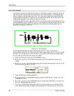
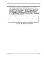
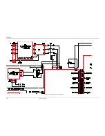
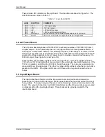
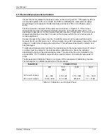
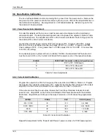
5.8 AC Power Board
The AC power assembly takes a 250V/500V DC input and generates a 150V/300V AC direct
c
oupled output. The AC power amplifier is a full bridge inverter with three paralleled IGBT‟s in
each leg for a total of twelve IGBT‟s. The switching frequency of the bridge is 37.5 kHz and this
frequency is smoothed out by two inductors that are mounted behind the input/output board and
several smoothing capacitors on the AC power board to provide a precision low frequency (16-
500 Hz) output. (See Figure 5-3 and Figure 5-5)
Three isolated 18V supplies provide power for the gate drives. The 18V is regulated down to
15V by three TO220 regulators that are mounted on three discrete sheet metal heat sinks. If the
15V is in regulation, an LED will be lit in front of each heat sink. There is a red, a green and an
orange LED, one for each supply. The other four green LED‟s will be lit when there is gate drive
present at the IGBT‟s. If the green LED‟s are not lit there will be no gate drive and hence no
output.
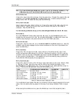
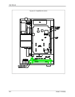
5.9 Input/Output Board
The input/output board holds a lot of the large components and provides interconnection
between the AC input, the DC-DC board, the AC power board and the output without the use of
heavy cables. The output relay and the output current metering circuit are also mounted on this
board. The output AC inductors, the DC-DC transformer and the DC output choke are mounted
on brackets behind the input/output board. These brackets also provide support for the
input/output board.
Содержание 10001i
Страница 2: ......
Страница 3: ......
Страница 6: ...ii This page intentionally left blank...
Страница 25: ...User Manual i Series iX Series 11 Parameter Specification Shock Designed to meet NSTA 1A transportation levels...
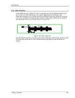
Страница 38: ...User Manual 24 i Series iX Series Figure 3 5 Rear Panel View for the 3001i 3001iX...
Страница 39: ...User Manual i Series iX Series 25 Figure 3 6 Rear Panel View for the 5001i 5001iX...
Страница 42: ...User Manual 28 i Series iX Series Figure 3 7 Connection For Single Power Source 5001iX i 3001iX i...
Страница 43: ...User Manual i Series iX Series 29 Figure 3 8 Functional Test Setup...
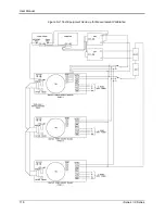
Страница 44: ...User Manual 30 i Series iX Series Figure 3 9 Single Phase 10000 VA System 10001iX i...
Страница 45: ...User Manual i Series iX Series 31 Figure 3 10 Three Phase 15000 VA System 15003iX i LK Three Controllers...
Страница 46: ...User Manual 32 i Series iX Series Figure 3 11 Single Phase 15000 VA System 15001iX i...
Страница 47: ...User Manual i Series iX Series 33 Figure 3 12 Three Phase 15000 VA system 15003iX i One Controller...
Страница 48: ...User Manual 34 i Series iX Series Figure 3 13 Connection With MODE Option...
Страница 49: ...User Manual i Series iX Series 35 Figure 3 14 Two Phase 10000 VA System 10002i LK Two Controllers...
Страница 50: ...User Manual 36 i Series iX Series Figure 3 15 Three Phase 9000 VA System 9003iX i One Controller...
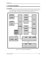
Страница 118: ...User Manual 104 i Series iX Series Figure 5 2 Power Source Module Block Diagram...
Страница 121: ...User Manual i Series iX Series 107 Figure 5 3 5001i Internal Layout...
Страница 122: ...User Manual 108 i Series iX Series Figure 5 4 Logic Board LED s...
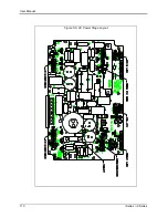
Страница 124: ...User Manual 110 i Series iX Series Figure 5 5 AC Power Stage Layout...
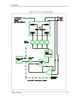
Страница 125: ...User Manual i Series iX Series 111 Figure 5 6 AC Control Logic Block Diagram...
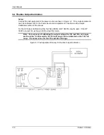
Страница 132: ...User Manual 118 i Series iX Series Figure 6 2 Test Equipment Hook up for Measurement Calibration...
Страница 138: ...User Manual 124 i Series iX Series Figure 6 3 Adjustment Location...
Страница 152: ...User Manual 138 i Series iX Series Figure 9 4 Voltage Modulation...
Страница 219: ...User Manual i Series iX Series 205 Figure 9 36 Example Connection With 5001iX and EOS 1...
Страница 220: ...User Manual 206 i Series iX Series Figure 9 37 Example Connection With Compliance Test System and EOS 1...
Страница 221: ...User Manual i Series iX Series 207 Figure 9 38 15003iX CTS EOS3 LR3...
Страница 222: ...User Manual 208 i Series iX Series Figure 9 39 15003iX 3 EOS3...
Страница 226: ...User Manual 212 i Series iX Series Figure 9 40 EOS3 Location of 70 80 Taps for each phase Lug 3 70 Lug 5 80...
Страница 233: ...User Manual i Series iX Series 219 Figure 9 41 Example Connection With MODE iX...
Страница 240: ...User Manual 226 i Series iX Series Figure 9 42 Example Connections With OMNI 1 18i...
Страница 241: ...User Manual i Series iX Series 227 Figure 9 43 Example Connections With OMNI 3 18i...
Страница 242: ...User Manual 228 i Series iX Series Figure 9 44 Schematic Showing OMNI 1 37i and1 37iJ Connected to 5001iX System...
Страница 243: ...User Manual i Series iX Series 229 Figure 9 45 Schematic Showing OMNI 3 37i Connected to 30003iX System...
Страница 249: ...User Manual i Series iX Series 235 9 7 4 Mechanical Dimensions Figure 9 49 XLS Module Dimensions...