


User Manual
i Series / iX Series
185
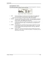
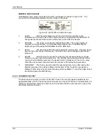
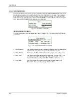
RUN SINGLE
RUN SINGLE command will run the test once. The Variation test is defined by the REDUCE TO,
FALL TIME, HOLD TIME and RISE TIME parameters. These parameters must be set before
starting the test. The following is a description of these parameters.
REDUCE
TO:
The lowest voltage level as a percentage of the nominal voltage. Thus, 0% is 0
Volts. 100% is full nominal voltage.
FALL TIME:
The time in seconds it will take the output to reach the REDUCE TO voltage.
Values must be entered in seconds. A 0.000 sec time may be used for abrupt
voltage drops instead of voltage sweeps to support Edition 2.0 of the test
standard. This requires firmware 2.38 or higher however.
HOLD TIME:
The time in seconds the output will hold at the REDUCE TO voltage. Values
must be entered in seconds.
RISE TIME:
The time in seconds the output will reach the NOMINAL voltage from the
REDUCE TO voltage. Values must be entered in seconds.
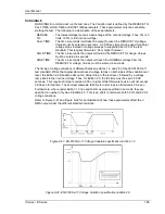
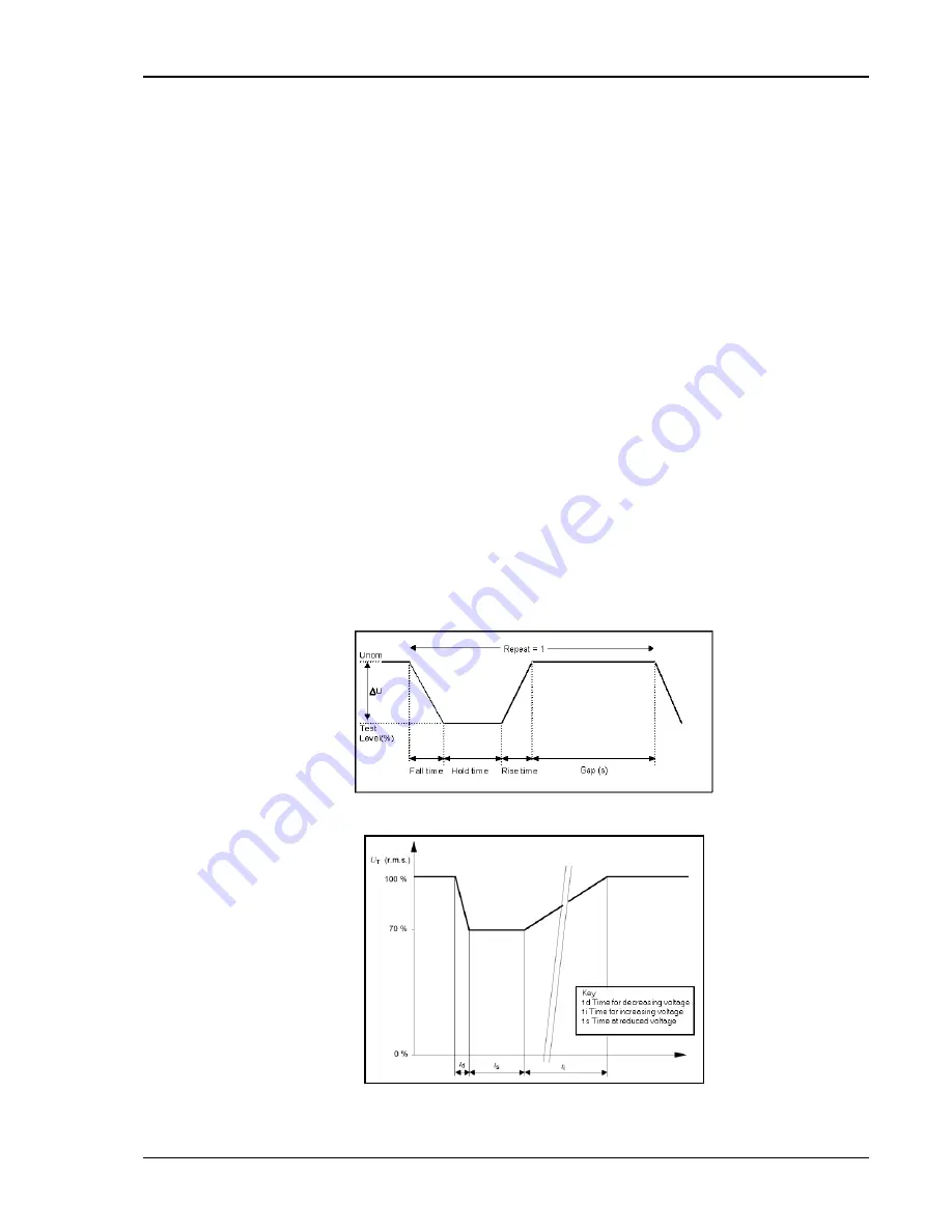
The timing of voltage variations is different between editions 1.0 and 2.0 of the IEC 61000-4-11
test standard. While the original standard used voltage ramps on both sides of the variation test
level, the Edition 2.0 standard calls out an abrupt drop to the test level, followed by a voltage
ramp back to the nominal voltage. Thus, for Edition 2.0, the fall time must be set to 0.000
seconds. This requires firmware revision 2.38 or higher. Older firmware revision will not accept
0.000 sec for fall time. The shortest allowable fall time for older revision firmware is 0.02 sec.
Furthermore, where under Edition 1.0 rise and fall times were specified in seconds, they are
specified in number of cycles in Edition 2.0. This is an effort to normalize both 50 Hz and 60 Hz
voltage variations.
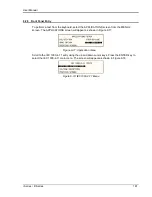
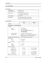
Refer to Figure 9-21 and Figure 9-22 for an illustration of how these parameters affect the V
RMS output under the different standard revisions.
Figure 9-21: EN 61000-4-11 Voltage Variation specification- Edition 1.0
Figure 9-22: EN 61000-4-11 Voltage Variation specification- Edition 2.0
Содержание 10001i
Страница 2: ......
Страница 3: ......
Страница 6: ...ii This page intentionally left blank...
Страница 25: ...User Manual i Series iX Series 11 Parameter Specification Shock Designed to meet NSTA 1A transportation levels...
Страница 38: ...User Manual 24 i Series iX Series Figure 3 5 Rear Panel View for the 3001i 3001iX...
Страница 39: ...User Manual i Series iX Series 25 Figure 3 6 Rear Panel View for the 5001i 5001iX...
Страница 42: ...User Manual 28 i Series iX Series Figure 3 7 Connection For Single Power Source 5001iX i 3001iX i...
Страница 43: ...User Manual i Series iX Series 29 Figure 3 8 Functional Test Setup...
Страница 44: ...User Manual 30 i Series iX Series Figure 3 9 Single Phase 10000 VA System 10001iX i...
Страница 45: ...User Manual i Series iX Series 31 Figure 3 10 Three Phase 15000 VA System 15003iX i LK Three Controllers...
Страница 46: ...User Manual 32 i Series iX Series Figure 3 11 Single Phase 15000 VA System 15001iX i...
Страница 47: ...User Manual i Series iX Series 33 Figure 3 12 Three Phase 15000 VA system 15003iX i One Controller...
Страница 48: ...User Manual 34 i Series iX Series Figure 3 13 Connection With MODE Option...
Страница 49: ...User Manual i Series iX Series 35 Figure 3 14 Two Phase 10000 VA System 10002i LK Two Controllers...
Страница 50: ...User Manual 36 i Series iX Series Figure 3 15 Three Phase 9000 VA System 9003iX i One Controller...
Страница 118: ...User Manual 104 i Series iX Series Figure 5 2 Power Source Module Block Diagram...
Страница 121: ...User Manual i Series iX Series 107 Figure 5 3 5001i Internal Layout...
Страница 122: ...User Manual 108 i Series iX Series Figure 5 4 Logic Board LED s...
Страница 124: ...User Manual 110 i Series iX Series Figure 5 5 AC Power Stage Layout...
Страница 125: ...User Manual i Series iX Series 111 Figure 5 6 AC Control Logic Block Diagram...
Страница 132: ...User Manual 118 i Series iX Series Figure 6 2 Test Equipment Hook up for Measurement Calibration...
Страница 138: ...User Manual 124 i Series iX Series Figure 6 3 Adjustment Location...
Страница 152: ...User Manual 138 i Series iX Series Figure 9 4 Voltage Modulation...
Страница 219: ...User Manual i Series iX Series 205 Figure 9 36 Example Connection With 5001iX and EOS 1...
Страница 220: ...User Manual 206 i Series iX Series Figure 9 37 Example Connection With Compliance Test System and EOS 1...
Страница 221: ...User Manual i Series iX Series 207 Figure 9 38 15003iX CTS EOS3 LR3...
Страница 222: ...User Manual 208 i Series iX Series Figure 9 39 15003iX 3 EOS3...
Страница 226: ...User Manual 212 i Series iX Series Figure 9 40 EOS3 Location of 70 80 Taps for each phase Lug 3 70 Lug 5 80...
Страница 233: ...User Manual i Series iX Series 219 Figure 9 41 Example Connection With MODE iX...
Страница 240: ...User Manual 226 i Series iX Series Figure 9 42 Example Connections With OMNI 1 18i...
Страница 241: ...User Manual i Series iX Series 227 Figure 9 43 Example Connections With OMNI 3 18i...
Страница 242: ...User Manual 228 i Series iX Series Figure 9 44 Schematic Showing OMNI 1 37i and1 37iJ Connected to 5001iX System...
Страница 243: ...User Manual i Series iX Series 229 Figure 9 45 Schematic Showing OMNI 3 37i Connected to 30003iX System...
Страница 249: ...User Manual i Series iX Series 235 9 7 4 Mechanical Dimensions Figure 9 49 XLS Module Dimensions...