User Manual
i Series / iX Series
9
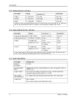
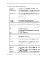
Parameter
Specification
Transient
Voltage: drop, step, sag, surge, sweep
Frequency: step, sag, surge, sweep
Voltage and Frequency: step, sweep
IEEE-488 Interface:
SH1, AH1, T6, L3, SR1, RL2, DC1, DT1
IEEE 488.2 and SCPI
Response time is 10 ms (typical)
RS232C Interface:
Bi-directional serial interface
9 pin D-shell connector
Handshake: CTS, RTS
Data bits: 7, 8
Stop bits: 1,2
Baud rate: 9600, 19200, 38400
IEEE 488.2 and SCPI
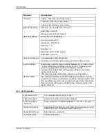
Current Limit Modes: Two selectable modes of operation.
Constant current and constant voltage with hold-off time and trip.
Function Strobe
Isolated open collector output available between pin 31 (High) and pin
14 (Low) of the System Interface connector (J22). Negative going
pulse on any programmed voltage or frequency change.
Function strobe output can be reassigned as trigger output when
running list transients.
This output requires a external DC supply and pull-up resistor.
Remote Inhibit
Also referred to as Remote On/Off. Digital input available on pin 36
and pin 27 (D-Common) of the System Interface connector (J22). The
Remote inhibit input can be used to open the output relay. The output
relay state is not latching so will return to the closed state when the
input is removed.
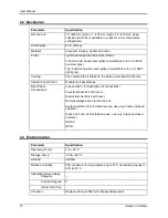
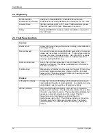
2.1.8 Unit Protection
Input Overcurrent:
Circuit breaker with shunt trip control.
Input Overvoltage:
Automatic shunt trip of input circuit breaker.
Input Overvoltage
Transients:
Surge protection to withstand EN50082-1 (IEC 801-4, 5) levels.
Output Overcurrent:
Adjustable level constant current mode with a maximum set point
between 0% and 10% above programmed value.
Output Short Circuit:
Peak and rms current limit.
Overtemperature:
Automatic shutdown.
Содержание 10001i
Страница 2: ......
Страница 3: ......
Страница 6: ...ii This page intentionally left blank...
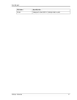
Страница 25: ...User Manual i Series iX Series 11 Parameter Specification Shock Designed to meet NSTA 1A transportation levels...
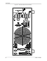
Страница 38: ...User Manual 24 i Series iX Series Figure 3 5 Rear Panel View for the 3001i 3001iX...
Страница 39: ...User Manual i Series iX Series 25 Figure 3 6 Rear Panel View for the 5001i 5001iX...
Страница 42: ...User Manual 28 i Series iX Series Figure 3 7 Connection For Single Power Source 5001iX i 3001iX i...
Страница 43: ...User Manual i Series iX Series 29 Figure 3 8 Functional Test Setup...
Страница 44: ...User Manual 30 i Series iX Series Figure 3 9 Single Phase 10000 VA System 10001iX i...
Страница 45: ...User Manual i Series iX Series 31 Figure 3 10 Three Phase 15000 VA System 15003iX i LK Three Controllers...
Страница 46: ...User Manual 32 i Series iX Series Figure 3 11 Single Phase 15000 VA System 15001iX i...
Страница 47: ...User Manual i Series iX Series 33 Figure 3 12 Three Phase 15000 VA system 15003iX i One Controller...
Страница 48: ...User Manual 34 i Series iX Series Figure 3 13 Connection With MODE Option...
Страница 49: ...User Manual i Series iX Series 35 Figure 3 14 Two Phase 10000 VA System 10002i LK Two Controllers...
Страница 50: ...User Manual 36 i Series iX Series Figure 3 15 Three Phase 9000 VA System 9003iX i One Controller...
Страница 118: ...User Manual 104 i Series iX Series Figure 5 2 Power Source Module Block Diagram...
Страница 121: ...User Manual i Series iX Series 107 Figure 5 3 5001i Internal Layout...
Страница 122: ...User Manual 108 i Series iX Series Figure 5 4 Logic Board LED s...
Страница 124: ...User Manual 110 i Series iX Series Figure 5 5 AC Power Stage Layout...
Страница 125: ...User Manual i Series iX Series 111 Figure 5 6 AC Control Logic Block Diagram...
Страница 132: ...User Manual 118 i Series iX Series Figure 6 2 Test Equipment Hook up for Measurement Calibration...
Страница 138: ...User Manual 124 i Series iX Series Figure 6 3 Adjustment Location...
Страница 152: ...User Manual 138 i Series iX Series Figure 9 4 Voltage Modulation...
Страница 219: ...User Manual i Series iX Series 205 Figure 9 36 Example Connection With 5001iX and EOS 1...
Страница 220: ...User Manual 206 i Series iX Series Figure 9 37 Example Connection With Compliance Test System and EOS 1...
Страница 221: ...User Manual i Series iX Series 207 Figure 9 38 15003iX CTS EOS3 LR3...
Страница 222: ...User Manual 208 i Series iX Series Figure 9 39 15003iX 3 EOS3...
Страница 226: ...User Manual 212 i Series iX Series Figure 9 40 EOS3 Location of 70 80 Taps for each phase Lug 3 70 Lug 5 80...
Страница 233: ...User Manual i Series iX Series 219 Figure 9 41 Example Connection With MODE iX...
Страница 240: ...User Manual 226 i Series iX Series Figure 9 42 Example Connections With OMNI 1 18i...
Страница 241: ...User Manual i Series iX Series 227 Figure 9 43 Example Connections With OMNI 3 18i...
Страница 242: ...User Manual 228 i Series iX Series Figure 9 44 Schematic Showing OMNI 1 37i and1 37iJ Connected to 5001iX System...
Страница 243: ...User Manual i Series iX Series 229 Figure 9 45 Schematic Showing OMNI 3 37i Connected to 30003iX System...
Страница 249: ...User Manual i Series iX Series 235 9 7 4 Mechanical Dimensions Figure 9 49 XLS Module Dimensions...

