User Manual
i Series / iX Series
323
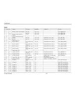
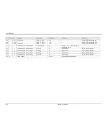
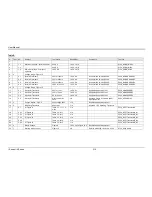
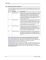
Number
Message String
Cause
Remedy
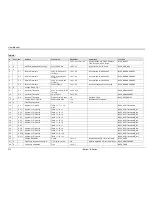
6
"Limit memory lost"
Hardware
configuration settings
lost.
Contact CI service department at
to obtain
instructions on restoring configuration
data.
7
"System memory lost"
Memory corrupted.
Recycle power.
8
"Calibration memory
lost"
Calibration data lost.
Contact CI service department at
to obtain
instructions on restoring calibration
data or recalibrate unit.
9
"Start angle must be
first sequence"
Start phase angle in
wrong place..
Start phase angles can only
programmed at the start of a transient
list. Once a transient is in progress,
phase angle cannot be changed.
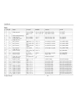
10
"Illegal for DC"
Operation not
possible in DC mode.
Switch to AC or AC+DC mode.
11
"Duplicate sequence"
N/A
N/A
12
"Too many sequence"
N/A
N/A
13
"Missing list
parameter"
One or more
transient list
parameters missing.
Check programmed lists.
14
"Voltage peak error "
Peak voltage
exceeds internal bus
voltage
This error may occur when selecting
user defined wave shapes with higher
crest factors. Reduce programmed
RMS value.
15
"Slew time exceed
dwell"
Time needed to slew
to final value is less
than dwell time.
Check dwell times in transient list
settings. Increase dwell time or
change slew rate for affected
parameter.
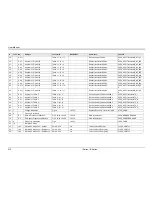
16
"Illegal during
transient"
Operation requested
not available while
transient is running.
Wait till transient execution is
completed or abort transient
execution first.
17
"Output relay must be
closed"
Operation not
possible with open
relay
Close relay before attempting
operation. E.g. transient execution
requires output relay to be closed.
18
"Trans. duration less
then 1msec"
Dwell time below
minimum or 1 msec
Increase dwell time to at least 1
msec.
19
"Clock and sync must
be internal"
Operation not
possible with external
clock
Switch to internal sync. (Default)
20
"Input buffer full"
Too much data
received.
Break up data in smaller blocks.
21
"EOS Fault"
Hardware error
reported by EOS
option
Cycle power on EOS to reset error. If
error persist, contact Contact CI
service department at
for repair.
22
"Waveform harmonics
limit"
Harmonic contents of
user defined wave
shape is too high and
could damage
amplifier output
stage.
Reduce harmonic content or reduce
fundamental frequency programmed.
Содержание 10001i
Страница 2: ......
Страница 3: ......
Страница 6: ...ii This page intentionally left blank...
Страница 25: ...User Manual i Series iX Series 11 Parameter Specification Shock Designed to meet NSTA 1A transportation levels...
Страница 38: ...User Manual 24 i Series iX Series Figure 3 5 Rear Panel View for the 3001i 3001iX...
Страница 39: ...User Manual i Series iX Series 25 Figure 3 6 Rear Panel View for the 5001i 5001iX...
Страница 42: ...User Manual 28 i Series iX Series Figure 3 7 Connection For Single Power Source 5001iX i 3001iX i...
Страница 43: ...User Manual i Series iX Series 29 Figure 3 8 Functional Test Setup...
Страница 44: ...User Manual 30 i Series iX Series Figure 3 9 Single Phase 10000 VA System 10001iX i...
Страница 45: ...User Manual i Series iX Series 31 Figure 3 10 Three Phase 15000 VA System 15003iX i LK Three Controllers...
Страница 46: ...User Manual 32 i Series iX Series Figure 3 11 Single Phase 15000 VA System 15001iX i...
Страница 47: ...User Manual i Series iX Series 33 Figure 3 12 Three Phase 15000 VA system 15003iX i One Controller...
Страница 48: ...User Manual 34 i Series iX Series Figure 3 13 Connection With MODE Option...
Страница 49: ...User Manual i Series iX Series 35 Figure 3 14 Two Phase 10000 VA System 10002i LK Two Controllers...
Страница 50: ...User Manual 36 i Series iX Series Figure 3 15 Three Phase 9000 VA System 9003iX i One Controller...
Страница 118: ...User Manual 104 i Series iX Series Figure 5 2 Power Source Module Block Diagram...
Страница 121: ...User Manual i Series iX Series 107 Figure 5 3 5001i Internal Layout...
Страница 122: ...User Manual 108 i Series iX Series Figure 5 4 Logic Board LED s...
Страница 124: ...User Manual 110 i Series iX Series Figure 5 5 AC Power Stage Layout...
Страница 125: ...User Manual i Series iX Series 111 Figure 5 6 AC Control Logic Block Diagram...
Страница 132: ...User Manual 118 i Series iX Series Figure 6 2 Test Equipment Hook up for Measurement Calibration...
Страница 138: ...User Manual 124 i Series iX Series Figure 6 3 Adjustment Location...
Страница 152: ...User Manual 138 i Series iX Series Figure 9 4 Voltage Modulation...
Страница 219: ...User Manual i Series iX Series 205 Figure 9 36 Example Connection With 5001iX and EOS 1...
Страница 220: ...User Manual 206 i Series iX Series Figure 9 37 Example Connection With Compliance Test System and EOS 1...
Страница 221: ...User Manual i Series iX Series 207 Figure 9 38 15003iX CTS EOS3 LR3...
Страница 222: ...User Manual 208 i Series iX Series Figure 9 39 15003iX 3 EOS3...
Страница 226: ...User Manual 212 i Series iX Series Figure 9 40 EOS3 Location of 70 80 Taps for each phase Lug 3 70 Lug 5 80...
Страница 233: ...User Manual i Series iX Series 219 Figure 9 41 Example Connection With MODE iX...
Страница 240: ...User Manual 226 i Series iX Series Figure 9 42 Example Connections With OMNI 1 18i...
Страница 241: ...User Manual i Series iX Series 227 Figure 9 43 Example Connections With OMNI 3 18i...
Страница 242: ...User Manual 228 i Series iX Series Figure 9 44 Schematic Showing OMNI 1 37i and1 37iJ Connected to 5001iX System...
Страница 243: ...User Manual i Series iX Series 229 Figure 9 45 Schematic Showing OMNI 3 37i Connected to 30003iX System...
Страница 249: ...User Manual i Series iX Series 235 9 7 4 Mechanical Dimensions Figure 9 49 XLS Module Dimensions...

