


User Manual
252
i Series / iX Series
This manual is
not
intended to elaborate on the intent or purpose of the immunity tests and the
expected behavior of the EUT as described in the MIL-STD-704 documents. It is assumed that
the end-user is familiar with the content of the MIL-STD-704 test standard.
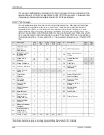
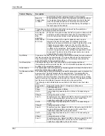
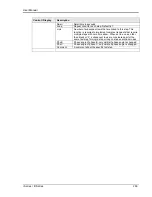
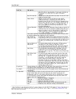
9.8.2.2 Test Coverage
The comprehensiveness of the test that can be performed with the
–704 option is determined
primarily by the capabilities of the power source used. Tests that are outside the hardware
capabilities of the power source used will not be enabled and cannot be selected. For these
tests, additional equipment may be required as indicated. The extent of coverage of the
–704
option as implemented on the IX Series platform is shown in the table below. Tests marked with
an „x‟ generally require additional hardware to be used. Tests marked „N/A‟ are not applicable to
the corresponding table. Tests marked with a „ ‟ are covered by at least one rev of the MIL-STD-
704.
No.
Description
Table
SAC
Table
TAC
Table
SVF
Table
TVF
Table
SXF
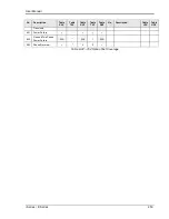
No.
Description
Table
LDC
Table
HDC
101
Load and Current
Harmonic
Measurements
101
Load Measurements
102
Steady State Limits
for Voltage and
Frequency
102
Steady State Limits for
Voltage
103
Voltage Phase
Difference
N/A
N/A
N/A
103
Voltage Distortion
Spectrum
X
X
104
Voltage Modulation
104
Total Ripple
X
X
105
Frequency Modulation
105
Normal Voltage
Transients
1
106
Voltage Distortion
Spectrum
X
X
X
X
X
201
Power Interrupt
107
Total Voltage
Distortion
301
Abnormal Steady State
Limits for Voltage
108
DC Voltage
Component
302
Abnormal Voltage
Transients
2
109
Normal Voltage
Transients
401
Emergency Limits for
Voltage
110
Normal Frequency
Transients
501
Starting Voltage
Transients
201
Power Interrupt
601
Power Failure
301
Abnormal Steady
State Limits for
Voltage and Freq.
602
Polarity Reversal
302
Abnormal Voltage
Transients
303
Abnormal Frequency
Transients
401
Emergency Steady
State Limits for
Voltage and Freq.
501
Starting Voltage
N/A
N/A
N/A
N/A
N/A
1
Note: Some restrictions apply due to voltage range limitations. See section 9.8.2.3 for details.
2
Note: Some restrictions apply due to voltage range limitations. See section 9.8.2.3 for details.
Содержание 10001i
Страница 2: ......
Страница 3: ......
Страница 6: ...ii This page intentionally left blank...
Страница 25: ...User Manual i Series iX Series 11 Parameter Specification Shock Designed to meet NSTA 1A transportation levels...
Страница 38: ...User Manual 24 i Series iX Series Figure 3 5 Rear Panel View for the 3001i 3001iX...
Страница 39: ...User Manual i Series iX Series 25 Figure 3 6 Rear Panel View for the 5001i 5001iX...
Страница 42: ...User Manual 28 i Series iX Series Figure 3 7 Connection For Single Power Source 5001iX i 3001iX i...
Страница 43: ...User Manual i Series iX Series 29 Figure 3 8 Functional Test Setup...
Страница 44: ...User Manual 30 i Series iX Series Figure 3 9 Single Phase 10000 VA System 10001iX i...
Страница 45: ...User Manual i Series iX Series 31 Figure 3 10 Three Phase 15000 VA System 15003iX i LK Three Controllers...
Страница 46: ...User Manual 32 i Series iX Series Figure 3 11 Single Phase 15000 VA System 15001iX i...
Страница 47: ...User Manual i Series iX Series 33 Figure 3 12 Three Phase 15000 VA system 15003iX i One Controller...
Страница 48: ...User Manual 34 i Series iX Series Figure 3 13 Connection With MODE Option...
Страница 49: ...User Manual i Series iX Series 35 Figure 3 14 Two Phase 10000 VA System 10002i LK Two Controllers...
Страница 50: ...User Manual 36 i Series iX Series Figure 3 15 Three Phase 9000 VA System 9003iX i One Controller...
Страница 118: ...User Manual 104 i Series iX Series Figure 5 2 Power Source Module Block Diagram...
Страница 121: ...User Manual i Series iX Series 107 Figure 5 3 5001i Internal Layout...
Страница 122: ...User Manual 108 i Series iX Series Figure 5 4 Logic Board LED s...
Страница 124: ...User Manual 110 i Series iX Series Figure 5 5 AC Power Stage Layout...
Страница 125: ...User Manual i Series iX Series 111 Figure 5 6 AC Control Logic Block Diagram...
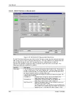
Страница 132: ...User Manual 118 i Series iX Series Figure 6 2 Test Equipment Hook up for Measurement Calibration...
Страница 138: ...User Manual 124 i Series iX Series Figure 6 3 Adjustment Location...
Страница 152: ...User Manual 138 i Series iX Series Figure 9 4 Voltage Modulation...
Страница 219: ...User Manual i Series iX Series 205 Figure 9 36 Example Connection With 5001iX and EOS 1...
Страница 220: ...User Manual 206 i Series iX Series Figure 9 37 Example Connection With Compliance Test System and EOS 1...
Страница 221: ...User Manual i Series iX Series 207 Figure 9 38 15003iX CTS EOS3 LR3...
Страница 222: ...User Manual 208 i Series iX Series Figure 9 39 15003iX 3 EOS3...
Страница 226: ...User Manual 212 i Series iX Series Figure 9 40 EOS3 Location of 70 80 Taps for each phase Lug 3 70 Lug 5 80...
Страница 233: ...User Manual i Series iX Series 219 Figure 9 41 Example Connection With MODE iX...
Страница 240: ...User Manual 226 i Series iX Series Figure 9 42 Example Connections With OMNI 1 18i...
Страница 241: ...User Manual i Series iX Series 227 Figure 9 43 Example Connections With OMNI 3 18i...
Страница 242: ...User Manual 228 i Series iX Series Figure 9 44 Schematic Showing OMNI 1 37i and1 37iJ Connected to 5001iX System...
Страница 243: ...User Manual i Series iX Series 229 Figure 9 45 Schematic Showing OMNI 3 37i Connected to 30003iX System...
Страница 249: ...User Manual i Series iX Series 235 9 7 4 Mechanical Dimensions Figure 9 49 XLS Module Dimensions...