


User Manual
i Series / iX Series
115
The Output Calibration Table is a summary of the output calibration procedure. The following
text is a detailed explanation of the procedure.
150 VAC Range DC Zero:
Press the PROGRAM key and select the 150 Range with the shuttle. Program the output to 0.0
volts. Go to the Output Calibration, press the PHASE key for the phase to be calibrated and
select the VOLT ZERO parameter. Close the Output Relay by pressing the OUTPUT ON/OFF
key. Monitor the DC output voltage with the external DVM. With shuttle control adjust the output
voltage for 0.0 ± 0.005 VDC.
150 VAC Range Full-scale:
Press the PROGRAM key and program 120.0 volts and 60 Hz. Go to the OUTPUT CAL screen
by choosing the PREVIOUS screen selection. Select the VOLT FS parameter and adjust the
output to 120.0 ±0.05 volts.
150 VAC Range HI Freq:
Press the PROGRAM key and program the output to 120.0 volts and 400 Hz. Go the OUTPUT
CAL screen and select the V HI FREQ parameter. Adjust the output with the shuttle for an
output of 120.0 ±0.05 volts. Repeat the 60 Hz and 400 Hz adjustments until the output is within
±0.05 volts of the programmed value.
300 VAC Range DC Zero:
Program the output to the 300 VAC Range by pressing and selecting the 300 Range with the
shuttle. Go the OUTPUT CAL screen, select the VOLT ZERO parameter and adjust the output
to 0.0 ±0.005 VDC.
300 VAC Range Volt Full-scale:
Program the output to 240.0 volts and 60 Hz. Go to the OUTPUT CAL screen and adjust VOLT
FS parameter for an output of 240.0 ±0.05 volts.
300 VAC Range Volt HI Freq:
Program the output to 240.0 volts and 400 Hz. Go to the OUTPUT CAL screen and select the V
HI FREQ parameter. Adjust the output with the shuttle for an output of 240.0 ±0.05 volts.
Repeat the 60 and 400 Hz adjustments until the output is within ±0.05 volts of the programmed
value.
300 VDC Range Volt Zero:
Press the PROGRAM key. Select the MORE option to go to the PROGRAM 2 screen. Highlight
the VOLT MODE parameter and select the DC Mode by moving the shuttle. Press the
PROGRAM key and program the 300 Range and 0.0 volts. Go to the OUTPUT CAL screen by
pressing the MENU key three times followed by pressing the ENTER key to display the OUTPUT
CAL screen. Adjust the VOLT ZERO for 0.0 ±0.005 volts DC.
300 VDC Range + Full-scale:
P 240.0 volts. Go to the OUTPUT CALIBRATION screen and adjust the VOLT FS
parameter for an output voltage of +240.0 ±0.05 volts DC.
300 VDC Range - Full-scale:
Program - 240.0 volts. Go the OUTPUT CALIBRATION screen and adjust the VOLT FS
parameter for an output voltage of -240.0 ±0.05 volts DC.
Содержание 10001i
Страница 2: ......
Страница 3: ......
Страница 6: ...ii This page intentionally left blank...
Страница 25: ...User Manual i Series iX Series 11 Parameter Specification Shock Designed to meet NSTA 1A transportation levels...
Страница 38: ...User Manual 24 i Series iX Series Figure 3 5 Rear Panel View for the 3001i 3001iX...
Страница 39: ...User Manual i Series iX Series 25 Figure 3 6 Rear Panel View for the 5001i 5001iX...
Страница 42: ...User Manual 28 i Series iX Series Figure 3 7 Connection For Single Power Source 5001iX i 3001iX i...
Страница 43: ...User Manual i Series iX Series 29 Figure 3 8 Functional Test Setup...
Страница 44: ...User Manual 30 i Series iX Series Figure 3 9 Single Phase 10000 VA System 10001iX i...
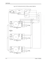
Страница 45: ...User Manual i Series iX Series 31 Figure 3 10 Three Phase 15000 VA System 15003iX i LK Three Controllers...
Страница 46: ...User Manual 32 i Series iX Series Figure 3 11 Single Phase 15000 VA System 15001iX i...
Страница 47: ...User Manual i Series iX Series 33 Figure 3 12 Three Phase 15000 VA system 15003iX i One Controller...
Страница 48: ...User Manual 34 i Series iX Series Figure 3 13 Connection With MODE Option...
Страница 49: ...User Manual i Series iX Series 35 Figure 3 14 Two Phase 10000 VA System 10002i LK Two Controllers...
Страница 50: ...User Manual 36 i Series iX Series Figure 3 15 Three Phase 9000 VA System 9003iX i One Controller...
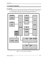
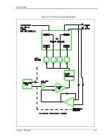
Страница 118: ...User Manual 104 i Series iX Series Figure 5 2 Power Source Module Block Diagram...
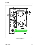
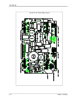
Страница 121: ...User Manual i Series iX Series 107 Figure 5 3 5001i Internal Layout...
Страница 122: ...User Manual 108 i Series iX Series Figure 5 4 Logic Board LED s...
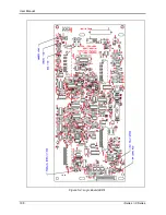
Страница 124: ...User Manual 110 i Series iX Series Figure 5 5 AC Power Stage Layout...
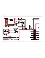
Страница 125: ...User Manual i Series iX Series 111 Figure 5 6 AC Control Logic Block Diagram...
Страница 132: ...User Manual 118 i Series iX Series Figure 6 2 Test Equipment Hook up for Measurement Calibration...
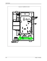
Страница 138: ...User Manual 124 i Series iX Series Figure 6 3 Adjustment Location...
Страница 152: ...User Manual 138 i Series iX Series Figure 9 4 Voltage Modulation...
Страница 219: ...User Manual i Series iX Series 205 Figure 9 36 Example Connection With 5001iX and EOS 1...
Страница 220: ...User Manual 206 i Series iX Series Figure 9 37 Example Connection With Compliance Test System and EOS 1...
Страница 221: ...User Manual i Series iX Series 207 Figure 9 38 15003iX CTS EOS3 LR3...
Страница 222: ...User Manual 208 i Series iX Series Figure 9 39 15003iX 3 EOS3...
Страница 226: ...User Manual 212 i Series iX Series Figure 9 40 EOS3 Location of 70 80 Taps for each phase Lug 3 70 Lug 5 80...
Страница 233: ...User Manual i Series iX Series 219 Figure 9 41 Example Connection With MODE iX...
Страница 240: ...User Manual 226 i Series iX Series Figure 9 42 Example Connections With OMNI 1 18i...
Страница 241: ...User Manual i Series iX Series 227 Figure 9 43 Example Connections With OMNI 3 18i...
Страница 242: ...User Manual 228 i Series iX Series Figure 9 44 Schematic Showing OMNI 1 37i and1 37iJ Connected to 5001iX System...
Страница 243: ...User Manual i Series iX Series 229 Figure 9 45 Schematic Showing OMNI 3 37i Connected to 30003iX System...
Страница 249: ...User Manual i Series iX Series 235 9 7 4 Mechanical Dimensions Figure 9 49 XLS Module Dimensions...