


User Manual
i Series / iX Series
83
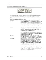
4.5 Standard Measurements
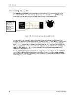
Standard measurements are always available through the MEAS key on the front panel. These
measurements are spread across two to four screens to enhance readability. Switching between
these screens can be done by successively pressing the MEAS button on the front panel. This
will cause the screen to cycle through all available measurement screens.
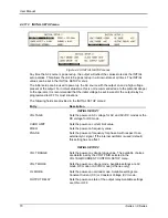
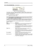
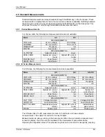
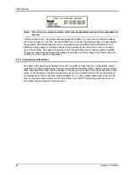
4.5.1 i Series Measurements
For i Series units, the following two measurement screens are available:
Mode
AC
DC
MEASUREMENTS 1
VOLTAGE
AC rms voltage
DC Voltage
CURRENT
AC rms current
DC Current
FREQUENCY
Frequency
n/a
POWER
Real power
power
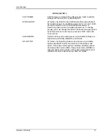
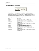
MEASUREMENTS 2
VA POWER
Apparent power
power
PEAK CURR
Highest AC current
found
Highest DC current
found
POWER FACT
Power factor
n/a
CREST FACT
Crest factor
n/a
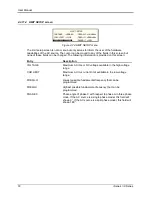
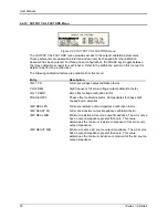
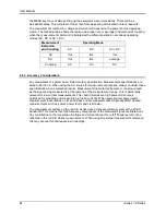
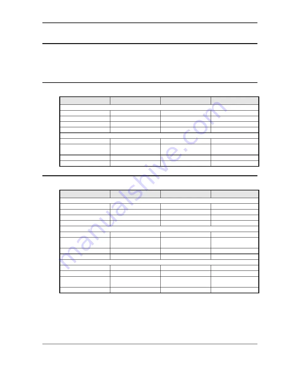
4.5.2 iX Series Measurements
For iX Series, the following four measurement screens are available:
Mode
AC
DC
AC+DC
MEASUREMENTS 1
VOLTAGE
AC rms voltage
DC Voltage
AC rms voltage
CURRENT
AC rms current
DC Current
AC rms current
FREQUENCY
Frequency
n/a
Frequency
POWER
Real power
n/a
n/a
MEASUREMENTS 2
VA POWER
Apparent power
power
Apparent power
PEAK CURR
Highest AC current
found
Highest DC current
found
Highest AC
current found
POWER FACT
Power factor
n/a
Power factor
CREST FACT
Crest factor
n/a
Crest factor
MEASUREMENTS 3
VOLT THD
Voltage distortion
n/a
Voltage distortion
CURR THD
Current distortion
n/a
Current distortion
INST PK CURR
Instantaneous peak
current
Highest DC current
found
Instantaneous
peak current
PHASE
Phase angle
n/a
Phase angle
The iX Series has a fourth measurement screen for harmonics and trace analysis
measurements. This subject is covered in the next chapter.
Measurements are always running in the background. When the user selects a measurement
screen for display, the AC source first updates all the measurement parameters before
displaying the requested screen. This process may take up to a second. Consequently, pressing
Содержание 10001i
Страница 2: ......
Страница 3: ......
Страница 6: ...ii This page intentionally left blank...
Страница 25: ...User Manual i Series iX Series 11 Parameter Specification Shock Designed to meet NSTA 1A transportation levels...
Страница 38: ...User Manual 24 i Series iX Series Figure 3 5 Rear Panel View for the 3001i 3001iX...
Страница 39: ...User Manual i Series iX Series 25 Figure 3 6 Rear Panel View for the 5001i 5001iX...
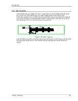
Страница 42: ...User Manual 28 i Series iX Series Figure 3 7 Connection For Single Power Source 5001iX i 3001iX i...
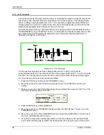
Страница 43: ...User Manual i Series iX Series 29 Figure 3 8 Functional Test Setup...
Страница 44: ...User Manual 30 i Series iX Series Figure 3 9 Single Phase 10000 VA System 10001iX i...
Страница 45: ...User Manual i Series iX Series 31 Figure 3 10 Three Phase 15000 VA System 15003iX i LK Three Controllers...
Страница 46: ...User Manual 32 i Series iX Series Figure 3 11 Single Phase 15000 VA System 15001iX i...
Страница 47: ...User Manual i Series iX Series 33 Figure 3 12 Three Phase 15000 VA system 15003iX i One Controller...
Страница 48: ...User Manual 34 i Series iX Series Figure 3 13 Connection With MODE Option...
Страница 49: ...User Manual i Series iX Series 35 Figure 3 14 Two Phase 10000 VA System 10002i LK Two Controllers...
Страница 50: ...User Manual 36 i Series iX Series Figure 3 15 Three Phase 9000 VA System 9003iX i One Controller...
Страница 118: ...User Manual 104 i Series iX Series Figure 5 2 Power Source Module Block Diagram...
Страница 121: ...User Manual i Series iX Series 107 Figure 5 3 5001i Internal Layout...
Страница 122: ...User Manual 108 i Series iX Series Figure 5 4 Logic Board LED s...
Страница 124: ...User Manual 110 i Series iX Series Figure 5 5 AC Power Stage Layout...
Страница 125: ...User Manual i Series iX Series 111 Figure 5 6 AC Control Logic Block Diagram...
Страница 132: ...User Manual 118 i Series iX Series Figure 6 2 Test Equipment Hook up for Measurement Calibration...
Страница 138: ...User Manual 124 i Series iX Series Figure 6 3 Adjustment Location...
Страница 152: ...User Manual 138 i Series iX Series Figure 9 4 Voltage Modulation...
Страница 219: ...User Manual i Series iX Series 205 Figure 9 36 Example Connection With 5001iX and EOS 1...
Страница 220: ...User Manual 206 i Series iX Series Figure 9 37 Example Connection With Compliance Test System and EOS 1...
Страница 221: ...User Manual i Series iX Series 207 Figure 9 38 15003iX CTS EOS3 LR3...
Страница 222: ...User Manual 208 i Series iX Series Figure 9 39 15003iX 3 EOS3...
Страница 226: ...User Manual 212 i Series iX Series Figure 9 40 EOS3 Location of 70 80 Taps for each phase Lug 3 70 Lug 5 80...
Страница 233: ...User Manual i Series iX Series 219 Figure 9 41 Example Connection With MODE iX...
Страница 240: ...User Manual 226 i Series iX Series Figure 9 42 Example Connections With OMNI 1 18i...
Страница 241: ...User Manual i Series iX Series 227 Figure 9 43 Example Connections With OMNI 3 18i...
Страница 242: ...User Manual 228 i Series iX Series Figure 9 44 Schematic Showing OMNI 1 37i and1 37iJ Connected to 5001iX System...
Страница 243: ...User Manual i Series iX Series 229 Figure 9 45 Schematic Showing OMNI 3 37i Connected to 30003iX System...
Страница 249: ...User Manual i Series iX Series 235 9 7 4 Mechanical Dimensions Figure 9 49 XLS Module Dimensions...