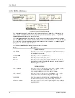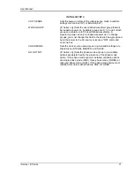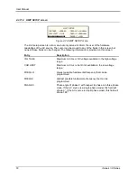
User Manual
58
i Series / iX Series
4.2.6.3 FREQUENCY SWEEP/STEP sub menu
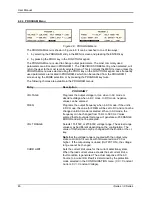
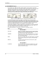
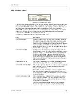
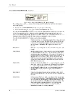
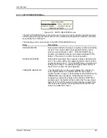
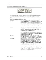
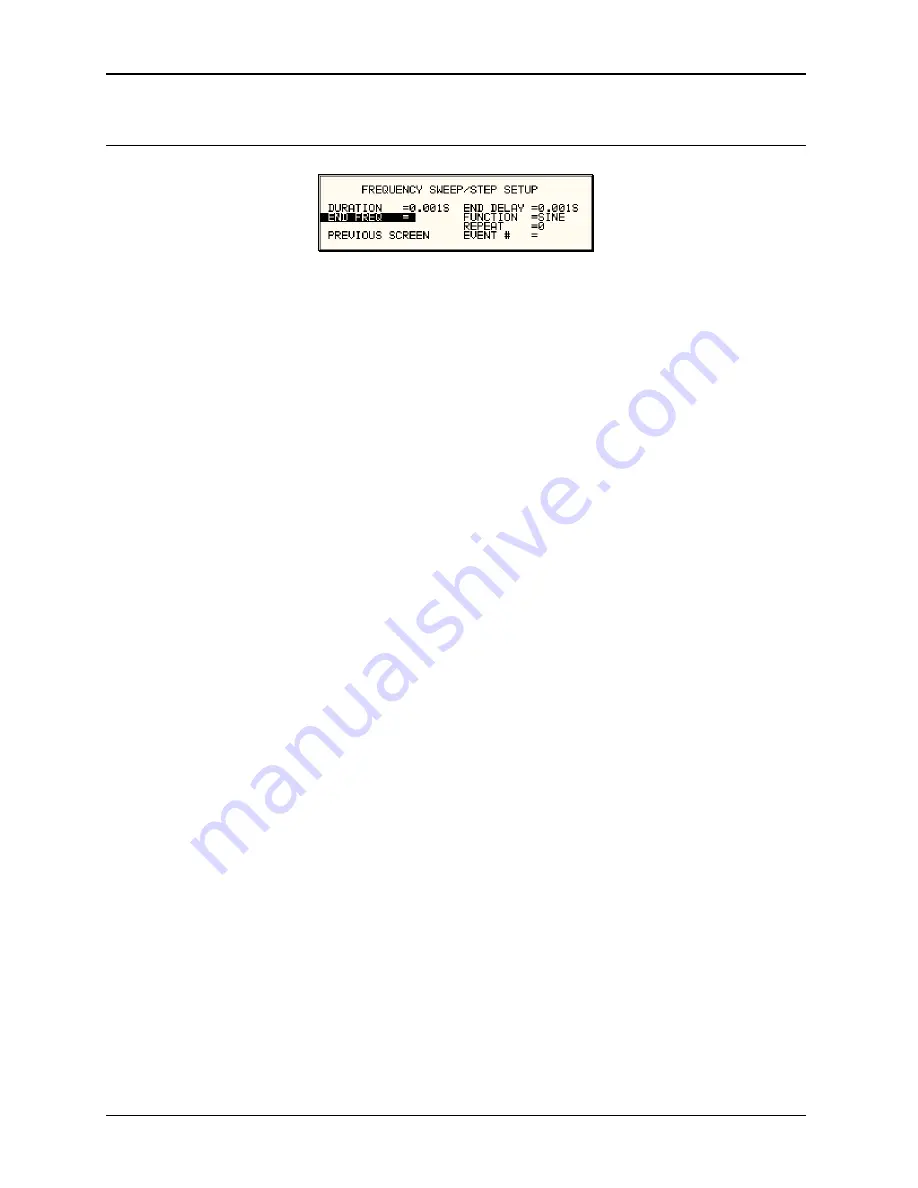
Figure 4-14: FREQUENCY SWEEP/STEP SETUP screen
The Voltage sweep and step screen shown in Figure 4-14 can be reached from the transient
screen as follows:
1. Scroll to the FREQ SWEEP/STEP entry using the up and down cursor keys.
2. Press the ENTER key to bring up the FREQ SWEEP/STEP screen.
The FREQ SWEEP/STEP screen has several data fields. All data fields that are blank to the right
of the equal sign must be filled or an error message will occur when trying to leave this screen.
The EVENT # is the last data field to be filled. Entering the event data field will cause the display
to return to the TRANSIENT screen where a new selection can be made.
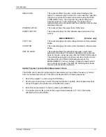
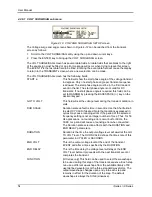
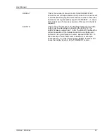
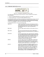
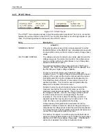
The FREQ SWEEP/STEP screen has the following fields:
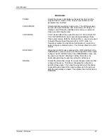
DURATION
Duration is amount of the time the output frequency will take to
reach the END FREQ level. Duration will define the slew rate of
the output frequency for the event. A duration of 0 seconds will
cause the output frequency to reach the end frequency
immediately.
END FREQ
This is the output frequency at the end of the transient event in
Hz.
END DELAY
This is the time delay the frequency will stay at END FREQ
before it proceeds with the next transient event or completes the
transient.
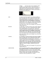
FUNCTION
[
iX Series only
] This field can be used to select the waveshape
to be used during this step of the transient sequence. Each step
can use a different waveshape from the available library of 50
user defined waveforms or the three standard waveforms. The
output waveshape changes upon entry into each step and
remains in effect for the duration of the step. The default
waveshape is always the SINE (sinewave).
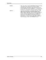
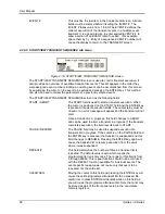
REPEAT
This is the number of times the FREQUENCY SWEEP/STEP
transient will repeat before it will proceed to the next event or
exit the transient. The number of times the transient event is
generated is equal to the 1. Leave this value at zero
if only one execution of this event in the list is required.
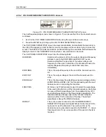
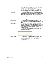
EVENT #
This must be the last item in the transient edit screen. All data
fields must be entered before inserting the EVENT #. The
EVENT # takes value from 1 to 99. The EVENT # defines the
order of execution of the transient events in a multiple event
transient. It is a good practice to enter spaced EVENT #‟s to
allow insertion of an EVENT later if needed. (For example,
space them by 5.) Entry of a sequence EVENT # number will
cause the display to return to the TRANSIENT screen.
Содержание 10001i
Страница 2: ......
Страница 3: ......
Страница 6: ...ii This page intentionally left blank...
Страница 25: ...User Manual i Series iX Series 11 Parameter Specification Shock Designed to meet NSTA 1A transportation levels...
Страница 38: ...User Manual 24 i Series iX Series Figure 3 5 Rear Panel View for the 3001i 3001iX...
Страница 39: ...User Manual i Series iX Series 25 Figure 3 6 Rear Panel View for the 5001i 5001iX...
Страница 42: ...User Manual 28 i Series iX Series Figure 3 7 Connection For Single Power Source 5001iX i 3001iX i...
Страница 43: ...User Manual i Series iX Series 29 Figure 3 8 Functional Test Setup...
Страница 44: ...User Manual 30 i Series iX Series Figure 3 9 Single Phase 10000 VA System 10001iX i...
Страница 45: ...User Manual i Series iX Series 31 Figure 3 10 Three Phase 15000 VA System 15003iX i LK Three Controllers...
Страница 46: ...User Manual 32 i Series iX Series Figure 3 11 Single Phase 15000 VA System 15001iX i...
Страница 47: ...User Manual i Series iX Series 33 Figure 3 12 Three Phase 15000 VA system 15003iX i One Controller...
Страница 48: ...User Manual 34 i Series iX Series Figure 3 13 Connection With MODE Option...
Страница 49: ...User Manual i Series iX Series 35 Figure 3 14 Two Phase 10000 VA System 10002i LK Two Controllers...
Страница 50: ...User Manual 36 i Series iX Series Figure 3 15 Three Phase 9000 VA System 9003iX i One Controller...
Страница 118: ...User Manual 104 i Series iX Series Figure 5 2 Power Source Module Block Diagram...
Страница 121: ...User Manual i Series iX Series 107 Figure 5 3 5001i Internal Layout...
Страница 122: ...User Manual 108 i Series iX Series Figure 5 4 Logic Board LED s...
Страница 124: ...User Manual 110 i Series iX Series Figure 5 5 AC Power Stage Layout...
Страница 125: ...User Manual i Series iX Series 111 Figure 5 6 AC Control Logic Block Diagram...
Страница 132: ...User Manual 118 i Series iX Series Figure 6 2 Test Equipment Hook up for Measurement Calibration...
Страница 138: ...User Manual 124 i Series iX Series Figure 6 3 Adjustment Location...
Страница 152: ...User Manual 138 i Series iX Series Figure 9 4 Voltage Modulation...
Страница 219: ...User Manual i Series iX Series 205 Figure 9 36 Example Connection With 5001iX and EOS 1...
Страница 220: ...User Manual 206 i Series iX Series Figure 9 37 Example Connection With Compliance Test System and EOS 1...
Страница 221: ...User Manual i Series iX Series 207 Figure 9 38 15003iX CTS EOS3 LR3...
Страница 222: ...User Manual 208 i Series iX Series Figure 9 39 15003iX 3 EOS3...
Страница 226: ...User Manual 212 i Series iX Series Figure 9 40 EOS3 Location of 70 80 Taps for each phase Lug 3 70 Lug 5 80...
Страница 233: ...User Manual i Series iX Series 219 Figure 9 41 Example Connection With MODE iX...
Страница 240: ...User Manual 226 i Series iX Series Figure 9 42 Example Connections With OMNI 1 18i...
Страница 241: ...User Manual i Series iX Series 227 Figure 9 43 Example Connections With OMNI 3 18i...
Страница 242: ...User Manual 228 i Series iX Series Figure 9 44 Schematic Showing OMNI 1 37i and1 37iJ Connected to 5001iX System...
Страница 243: ...User Manual i Series iX Series 229 Figure 9 45 Schematic Showing OMNI 3 37i Connected to 30003iX System...
Страница 249: ...User Manual i Series iX Series 235 9 7 4 Mechanical Dimensions Figure 9 49 XLS Module Dimensions...

