


User Manual
i Series / iX Series
187
9.3 IEC 61000-4-13 Option
9.3.1 General
The IEC413 option is capable of performing IEC 61000-4 section 13 Harmonics and inter
harmonics low frequency immunity tests. The tests are based on IEC 61000-4-13:2002-03, First
Edition. It is assumed that the user has a copy of the test standard available. This manual
section only cover operation of the
–413 option from the front-panel of the iX Series power
source.
Note 1:
The initial release of the
–413 option for the iX Series power sources was based on a
draft version (CDV) of the IEC 61000-4-13 standard. Minor changes were made between the
CDV draft and the final released version. Units with firmware revision 2.37 or higher conform to
the official released IEC standard. Units with older firmware conform to the draft version. A
firmware upgrade can be ordered through California Instruments‟ service department by
contacting
and requesting part number CIC463. Provide the model and
serial number of the unit (master unit in multi-box systems) to ensure the correct firmware is
provided. The firmware revision is displayed on the LCD screen immediately after power up for a
few seconds. It can also be queried over the bus using the “*IDN?” command.
Where relevant, the requirement for the correct firmware revision to obtain specific test modes is
indicated in this manual.
Note 2:
The
–413 option is only available on iX Series AC power sources, not i Series. It is
possible to upgrade most i Series AC source to an iX Series and add the
–413 option. Contact
the California Instruments service department for information.
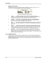
9.3.2 Initial Setup
The user must set the operating voltage and close the output relay prior to the start of test. The
following set of parameters must be set before the start of test.
1. Frequency to 50 or 60 Hz.
2. Voltage mode to AC.
3. Waveform to sine wave.
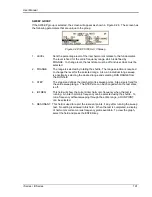
9.3.3 Tests Performed
The IEC61000-4-13 test consists of several types of tests. These tests can be run individually or
in sequence (ALL). The following tests are available:
1. Harmonic combination test flat curve and over swing.
2. Sweep in frequency and resonance frequency detection.
3. Individual harmonics and inter harmonics.
4. Meister curve test (Firmware revision 2.37 or higher required)
Содержание 10001i
Страница 2: ......
Страница 3: ......
Страница 6: ...ii This page intentionally left blank...
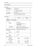
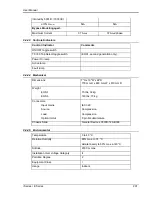
Страница 25: ...User Manual i Series iX Series 11 Parameter Specification Shock Designed to meet NSTA 1A transportation levels...
Страница 38: ...User Manual 24 i Series iX Series Figure 3 5 Rear Panel View for the 3001i 3001iX...
Страница 39: ...User Manual i Series iX Series 25 Figure 3 6 Rear Panel View for the 5001i 5001iX...
Страница 42: ...User Manual 28 i Series iX Series Figure 3 7 Connection For Single Power Source 5001iX i 3001iX i...
Страница 43: ...User Manual i Series iX Series 29 Figure 3 8 Functional Test Setup...
Страница 44: ...User Manual 30 i Series iX Series Figure 3 9 Single Phase 10000 VA System 10001iX i...
Страница 45: ...User Manual i Series iX Series 31 Figure 3 10 Three Phase 15000 VA System 15003iX i LK Three Controllers...
Страница 46: ...User Manual 32 i Series iX Series Figure 3 11 Single Phase 15000 VA System 15001iX i...
Страница 47: ...User Manual i Series iX Series 33 Figure 3 12 Three Phase 15000 VA system 15003iX i One Controller...
Страница 48: ...User Manual 34 i Series iX Series Figure 3 13 Connection With MODE Option...
Страница 49: ...User Manual i Series iX Series 35 Figure 3 14 Two Phase 10000 VA System 10002i LK Two Controllers...
Страница 50: ...User Manual 36 i Series iX Series Figure 3 15 Three Phase 9000 VA System 9003iX i One Controller...
Страница 118: ...User Manual 104 i Series iX Series Figure 5 2 Power Source Module Block Diagram...
Страница 121: ...User Manual i Series iX Series 107 Figure 5 3 5001i Internal Layout...
Страница 122: ...User Manual 108 i Series iX Series Figure 5 4 Logic Board LED s...
Страница 124: ...User Manual 110 i Series iX Series Figure 5 5 AC Power Stage Layout...
Страница 125: ...User Manual i Series iX Series 111 Figure 5 6 AC Control Logic Block Diagram...
Страница 132: ...User Manual 118 i Series iX Series Figure 6 2 Test Equipment Hook up for Measurement Calibration...
Страница 138: ...User Manual 124 i Series iX Series Figure 6 3 Adjustment Location...
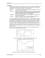
Страница 152: ...User Manual 138 i Series iX Series Figure 9 4 Voltage Modulation...
Страница 219: ...User Manual i Series iX Series 205 Figure 9 36 Example Connection With 5001iX and EOS 1...
Страница 220: ...User Manual 206 i Series iX Series Figure 9 37 Example Connection With Compliance Test System and EOS 1...
Страница 221: ...User Manual i Series iX Series 207 Figure 9 38 15003iX CTS EOS3 LR3...
Страница 222: ...User Manual 208 i Series iX Series Figure 9 39 15003iX 3 EOS3...
Страница 226: ...User Manual 212 i Series iX Series Figure 9 40 EOS3 Location of 70 80 Taps for each phase Lug 3 70 Lug 5 80...
Страница 233: ...User Manual i Series iX Series 219 Figure 9 41 Example Connection With MODE iX...
Страница 240: ...User Manual 226 i Series iX Series Figure 9 42 Example Connections With OMNI 1 18i...
Страница 241: ...User Manual i Series iX Series 227 Figure 9 43 Example Connections With OMNI 3 18i...
Страница 242: ...User Manual 228 i Series iX Series Figure 9 44 Schematic Showing OMNI 1 37i and1 37iJ Connected to 5001iX System...
Страница 243: ...User Manual i Series iX Series 229 Figure 9 45 Schematic Showing OMNI 3 37i Connected to 30003iX System...
Страница 249: ...User Manual i Series iX Series 235 9 7 4 Mechanical Dimensions Figure 9 49 XLS Module Dimensions...