


User Manual
i Series / iX Series
81
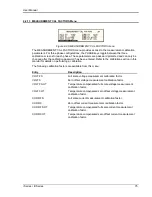
4.4.5 RMS Amplitude Restrictions
The output of a sinewave may be programmed to the full rms value of the voltage range
selected. If the AC source is in the 300 V range, the maximum programmable rms voltage is 300
Volt. If a custom waveform is used however, the maximum programmable rms voltage may be
less than the maximum range value. The voltage range limit is based on the use of a sinewave
with a 1.414 crest factor. A 300 V rms sinewave has a 424 Volt peak voltage. The AC source has
a maximum peak voltage capability that is determined by the selected voltage range. If the user
selects a custom waveform with a crest factor that is higher than 1.414, the peak voltage would
exceed this maximum if the rms voltage were to be programmed at 300 V rms.
The iX Series automatically limits the maximum allowable programmed rms voltage of a any
custom waveform by calculating the crest factor of the selected waveform and controlling the rms
limit accordingly. Thus, each custom waveform may have a different maximum rms value. The iX
controller will prevent the user from programming the rms voltage above this limit. If a value is
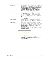
entered in the
PROGRAM 1 menu above this value, a “Voltage peak error” message is
generated.
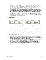
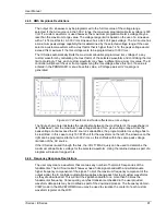
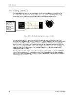
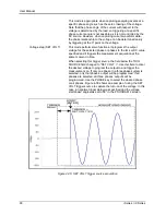
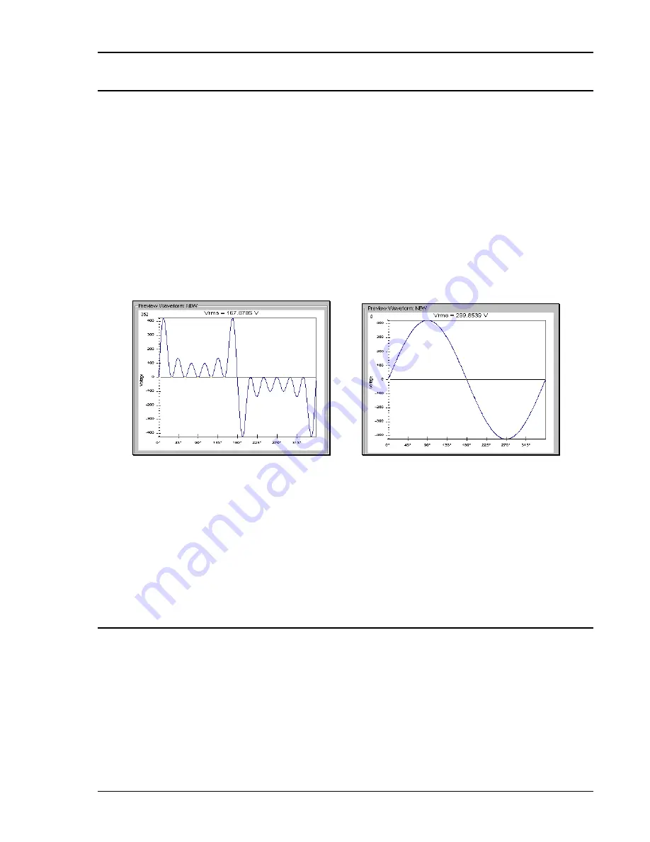
Figure 4-31: Waveform crest factor affects max. rms voltage
The figure shown here illustrates the relationship between the crest factor of the waveshape (or
its “peakiness”) and the maximum peak voltage allowed for a given voltage range. Since the
peak voltage cannot exceed the AC source‟s capabilities, the programmable rms voltage has to
be restricted, in this case to only 167.8785 volt for the waveform on the left. The sinewave on the
right can be programmed to the full 300 V rms as this still falls within the same peak voltage
limitation of the AC source.
If the iX Series is used through the bus, the :VOLT? MAX query can be used to determine the
maximum allowable rms voltage for the selected waveform. Using the returned value as part of a
program will prevent range errors.
4.4.6 Frequency Response Restrictions
The user may create a waveform that contains any number of harmonic frequencies of the
fundamental. The AC Source itself however has a finite signal bandwidth and will attenuate
higher frequency components of the signal. To limit the maximum frequency component of the
output signal, the iX controller automatically applies a band-pass filter to all custom waveforms
as they are downloaded. This will limit the signal bandwidth to no more than 50 times the
fundamental frequency. Consequently, very fast transients embedded in the user provided
waveform data points may be modified as part of the download process. The frequency domain
VIEW mode in the WAVEFORMS menu may be used to visualize the content of each custom
waveform register on the LCD.
Содержание 10001i
Страница 2: ......
Страница 3: ......
Страница 6: ...ii This page intentionally left blank...
Страница 25: ...User Manual i Series iX Series 11 Parameter Specification Shock Designed to meet NSTA 1A transportation levels...
Страница 38: ...User Manual 24 i Series iX Series Figure 3 5 Rear Panel View for the 3001i 3001iX...
Страница 39: ...User Manual i Series iX Series 25 Figure 3 6 Rear Panel View for the 5001i 5001iX...
Страница 42: ...User Manual 28 i Series iX Series Figure 3 7 Connection For Single Power Source 5001iX i 3001iX i...
Страница 43: ...User Manual i Series iX Series 29 Figure 3 8 Functional Test Setup...
Страница 44: ...User Manual 30 i Series iX Series Figure 3 9 Single Phase 10000 VA System 10001iX i...
Страница 45: ...User Manual i Series iX Series 31 Figure 3 10 Three Phase 15000 VA System 15003iX i LK Three Controllers...
Страница 46: ...User Manual 32 i Series iX Series Figure 3 11 Single Phase 15000 VA System 15001iX i...
Страница 47: ...User Manual i Series iX Series 33 Figure 3 12 Three Phase 15000 VA system 15003iX i One Controller...
Страница 48: ...User Manual 34 i Series iX Series Figure 3 13 Connection With MODE Option...
Страница 49: ...User Manual i Series iX Series 35 Figure 3 14 Two Phase 10000 VA System 10002i LK Two Controllers...
Страница 50: ...User Manual 36 i Series iX Series Figure 3 15 Three Phase 9000 VA System 9003iX i One Controller...
Страница 118: ...User Manual 104 i Series iX Series Figure 5 2 Power Source Module Block Diagram...
Страница 121: ...User Manual i Series iX Series 107 Figure 5 3 5001i Internal Layout...
Страница 122: ...User Manual 108 i Series iX Series Figure 5 4 Logic Board LED s...
Страница 124: ...User Manual 110 i Series iX Series Figure 5 5 AC Power Stage Layout...
Страница 125: ...User Manual i Series iX Series 111 Figure 5 6 AC Control Logic Block Diagram...
Страница 132: ...User Manual 118 i Series iX Series Figure 6 2 Test Equipment Hook up for Measurement Calibration...
Страница 138: ...User Manual 124 i Series iX Series Figure 6 3 Adjustment Location...
Страница 152: ...User Manual 138 i Series iX Series Figure 9 4 Voltage Modulation...
Страница 219: ...User Manual i Series iX Series 205 Figure 9 36 Example Connection With 5001iX and EOS 1...
Страница 220: ...User Manual 206 i Series iX Series Figure 9 37 Example Connection With Compliance Test System and EOS 1...
Страница 221: ...User Manual i Series iX Series 207 Figure 9 38 15003iX CTS EOS3 LR3...
Страница 222: ...User Manual 208 i Series iX Series Figure 9 39 15003iX 3 EOS3...
Страница 226: ...User Manual 212 i Series iX Series Figure 9 40 EOS3 Location of 70 80 Taps for each phase Lug 3 70 Lug 5 80...
Страница 233: ...User Manual i Series iX Series 219 Figure 9 41 Example Connection With MODE iX...
Страница 240: ...User Manual 226 i Series iX Series Figure 9 42 Example Connections With OMNI 1 18i...
Страница 241: ...User Manual i Series iX Series 227 Figure 9 43 Example Connections With OMNI 3 18i...
Страница 242: ...User Manual 228 i Series iX Series Figure 9 44 Schematic Showing OMNI 1 37i and1 37iJ Connected to 5001iX System...
Страница 243: ...User Manual i Series iX Series 229 Figure 9 45 Schematic Showing OMNI 3 37i Connected to 30003iX System...
Страница 249: ...User Manual i Series iX Series 235 9 7 4 Mechanical Dimensions Figure 9 49 XLS Module Dimensions...