User Manual
i Series / iX Series
267
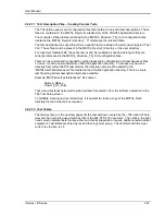
9.8.2.11 Test Description Files
– Creating Custom Tests
The 704 option uses a set of configuration files that contain the relevant test descriptions. These
files are contained in the MS704_Rev(A-F) subdirectory of the CIGUI32 application directory.
The contents of these tables is defined by the “MS704_Structure_Tbl_X.ini” configuration files
located in the MS704_Rev(A-
F) directory. “X” references the relevant table.
The test description files used to perform a specific test are listed in the last column labeled “Test
File”. These files must be present in the MS704_Rev(A-F) directory or the user directory.
For customer created tests, these file names can be renamed as needed as long as they are
correctly referenced in the MS704_Structure_Tbl_X.ini configuration files.
Tests can be customized as needed by editing these table configuration and test sequence files.
To do so, create a new subdirectory under the application directory. To access any new sub
directory from within the 704 test window, the directory name must be added to the
“MS704UserTestLibraries.txt” file located in the CIGui32 application directory. This is a simple
text file listing all test description directories available.
Example “MS704UserTestLibraries.txt” file content:
MyNew_DBase
Dummy_Dir_Entry
These two directories listed will now be available for selection from the AirFrame selection in the
704 Test Setup screen.
To facilitate creating new test directories, it is easiest to create a copy of the MS704_RevF
directory first and rename it as required.
9.8.2.12 Test Tables
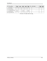
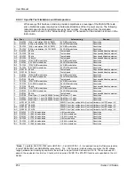
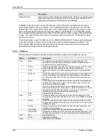
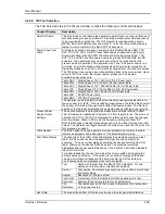
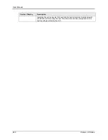
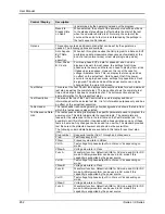
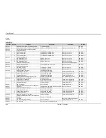
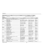
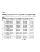
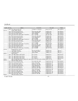
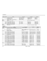
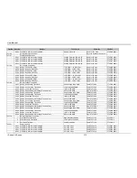
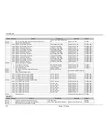
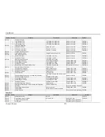
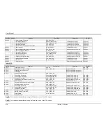
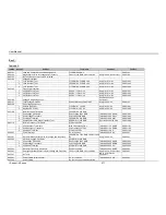
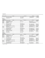
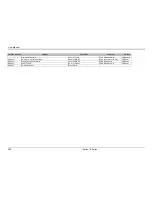
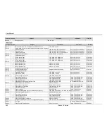
The tables shown on the next few pages list the test sections covered by the
–704 option. Where
relevant, the numbering used matches that of the MIL-STD-704 document. The notes in the right
hand column indicate tests that are either not directly supported or require additional external test
equipment. Test tables are listed by rev and then by power group. The list starts with the most
current rev to date, rev F.
Содержание 10001i
Страница 2: ......
Страница 3: ......
Страница 6: ...ii This page intentionally left blank...
Страница 25: ...User Manual i Series iX Series 11 Parameter Specification Shock Designed to meet NSTA 1A transportation levels...
Страница 38: ...User Manual 24 i Series iX Series Figure 3 5 Rear Panel View for the 3001i 3001iX...
Страница 39: ...User Manual i Series iX Series 25 Figure 3 6 Rear Panel View for the 5001i 5001iX...
Страница 42: ...User Manual 28 i Series iX Series Figure 3 7 Connection For Single Power Source 5001iX i 3001iX i...
Страница 43: ...User Manual i Series iX Series 29 Figure 3 8 Functional Test Setup...
Страница 44: ...User Manual 30 i Series iX Series Figure 3 9 Single Phase 10000 VA System 10001iX i...
Страница 45: ...User Manual i Series iX Series 31 Figure 3 10 Three Phase 15000 VA System 15003iX i LK Three Controllers...
Страница 46: ...User Manual 32 i Series iX Series Figure 3 11 Single Phase 15000 VA System 15001iX i...
Страница 47: ...User Manual i Series iX Series 33 Figure 3 12 Three Phase 15000 VA system 15003iX i One Controller...
Страница 48: ...User Manual 34 i Series iX Series Figure 3 13 Connection With MODE Option...
Страница 49: ...User Manual i Series iX Series 35 Figure 3 14 Two Phase 10000 VA System 10002i LK Two Controllers...
Страница 50: ...User Manual 36 i Series iX Series Figure 3 15 Three Phase 9000 VA System 9003iX i One Controller...
Страница 118: ...User Manual 104 i Series iX Series Figure 5 2 Power Source Module Block Diagram...
Страница 121: ...User Manual i Series iX Series 107 Figure 5 3 5001i Internal Layout...
Страница 122: ...User Manual 108 i Series iX Series Figure 5 4 Logic Board LED s...
Страница 124: ...User Manual 110 i Series iX Series Figure 5 5 AC Power Stage Layout...
Страница 125: ...User Manual i Series iX Series 111 Figure 5 6 AC Control Logic Block Diagram...
Страница 132: ...User Manual 118 i Series iX Series Figure 6 2 Test Equipment Hook up for Measurement Calibration...
Страница 138: ...User Manual 124 i Series iX Series Figure 6 3 Adjustment Location...
Страница 152: ...User Manual 138 i Series iX Series Figure 9 4 Voltage Modulation...
Страница 219: ...User Manual i Series iX Series 205 Figure 9 36 Example Connection With 5001iX and EOS 1...
Страница 220: ...User Manual 206 i Series iX Series Figure 9 37 Example Connection With Compliance Test System and EOS 1...
Страница 221: ...User Manual i Series iX Series 207 Figure 9 38 15003iX CTS EOS3 LR3...
Страница 222: ...User Manual 208 i Series iX Series Figure 9 39 15003iX 3 EOS3...
Страница 226: ...User Manual 212 i Series iX Series Figure 9 40 EOS3 Location of 70 80 Taps for each phase Lug 3 70 Lug 5 80...
Страница 233: ...User Manual i Series iX Series 219 Figure 9 41 Example Connection With MODE iX...
Страница 240: ...User Manual 226 i Series iX Series Figure 9 42 Example Connections With OMNI 1 18i...
Страница 241: ...User Manual i Series iX Series 227 Figure 9 43 Example Connections With OMNI 3 18i...
Страница 242: ...User Manual 228 i Series iX Series Figure 9 44 Schematic Showing OMNI 1 37i and1 37iJ Connected to 5001iX System...
Страница 243: ...User Manual i Series iX Series 229 Figure 9 45 Schematic Showing OMNI 3 37i Connected to 30003iX System...
Страница 249: ...User Manual i Series iX Series 235 9 7 4 Mechanical Dimensions Figure 9 49 XLS Module Dimensions...

