User Manual
224
i Series / iX Series
module. The selector card may be removed from the input module by removing the line cord,
sliding the plastic window to the left, and extracting the card.
For the Omni 1-18i and 3-18i the selector card is marked 100/220 on one side and 120/240 on
the opposite side. OMNI 1-18i and 3-18i may be operated from a 115 volt line by selecting the
120 volt range. It may be operated from 230 volts by selecting the 240 volt range. The 100 volt
and 220 volt ranges are not active.
The selected range is the one that is marked on the upper left side of the selector card as the
card is slid into the IEC 320 module.
The OMNI 1-37i, 1-37iJ and 3-37i are designed to operate on either 115V or 230V AC power.
The input voltage is user-selectable by orienting the input selector module inside the rear panel
power entry module. To change input voltage proceed as outlined below.
Note that attempting to operate the OMNI from an input range that does not match the
actual AC power voltage may cause permanent damage to the unit.
9.6.5 Voltage Range Configuration for the OMNI 1-37i, 1-37iJ and OMNI 3-37i
To change input range:
1. Remove power cord from input module.
2. Pry cover loose with a small screwdriver.
3. Pull out fuse holder, prying with a screwdriver will be necessary.
4. Orient the red fuse holder so that the desired voltage shows through the window. It is
necessary that the fuse always sits on the top side of the fuse holder when it is re-inserted
into the module. Likewise, the shorting clip must always be on the bottom of the fuse holder.
For example, if the input voltage is being changed from 115 to 230, the fuse holder must first be
removed, and then the clip and the fuse must swap location. The fuse assembly can then be
inserted back into the input module.
9.6.5.1 Mechanical Installation
The OMNI has been designed for rack mounting in a standard 19 inch rack. The unit should be
supported from the bottom with a shelf-track or supported from the sides with optional rack
slides.
The cooling fans at the rear of the unit must be free of any obstructions that would interfere with
the flow of air. A 2.5 inch clearance should be maintained between the rear of the unit and the
rear panel of the mounting cabinet. Also, the air intake holes on the sides of the power chassis
must not be obstructed.
9.6.5.2 Output Wiring
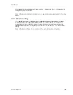
The OMNI impedance network is wired in series with the output of specified California
Instruments power sources or power source systems. The OMNI terminal block marked
SOURCE should be wired to the output of the power source/system. The terminal block marked
Содержание 10001i
Страница 2: ......
Страница 3: ......
Страница 6: ...ii This page intentionally left blank...
Страница 25: ...User Manual i Series iX Series 11 Parameter Specification Shock Designed to meet NSTA 1A transportation levels...
Страница 38: ...User Manual 24 i Series iX Series Figure 3 5 Rear Panel View for the 3001i 3001iX...
Страница 39: ...User Manual i Series iX Series 25 Figure 3 6 Rear Panel View for the 5001i 5001iX...
Страница 42: ...User Manual 28 i Series iX Series Figure 3 7 Connection For Single Power Source 5001iX i 3001iX i...
Страница 43: ...User Manual i Series iX Series 29 Figure 3 8 Functional Test Setup...
Страница 44: ...User Manual 30 i Series iX Series Figure 3 9 Single Phase 10000 VA System 10001iX i...
Страница 45: ...User Manual i Series iX Series 31 Figure 3 10 Three Phase 15000 VA System 15003iX i LK Three Controllers...
Страница 46: ...User Manual 32 i Series iX Series Figure 3 11 Single Phase 15000 VA System 15001iX i...
Страница 47: ...User Manual i Series iX Series 33 Figure 3 12 Three Phase 15000 VA system 15003iX i One Controller...
Страница 48: ...User Manual 34 i Series iX Series Figure 3 13 Connection With MODE Option...
Страница 49: ...User Manual i Series iX Series 35 Figure 3 14 Two Phase 10000 VA System 10002i LK Two Controllers...
Страница 50: ...User Manual 36 i Series iX Series Figure 3 15 Three Phase 9000 VA System 9003iX i One Controller...
Страница 118: ...User Manual 104 i Series iX Series Figure 5 2 Power Source Module Block Diagram...
Страница 121: ...User Manual i Series iX Series 107 Figure 5 3 5001i Internal Layout...
Страница 122: ...User Manual 108 i Series iX Series Figure 5 4 Logic Board LED s...
Страница 124: ...User Manual 110 i Series iX Series Figure 5 5 AC Power Stage Layout...
Страница 125: ...User Manual i Series iX Series 111 Figure 5 6 AC Control Logic Block Diagram...
Страница 132: ...User Manual 118 i Series iX Series Figure 6 2 Test Equipment Hook up for Measurement Calibration...
Страница 138: ...User Manual 124 i Series iX Series Figure 6 3 Adjustment Location...
Страница 152: ...User Manual 138 i Series iX Series Figure 9 4 Voltage Modulation...
Страница 219: ...User Manual i Series iX Series 205 Figure 9 36 Example Connection With 5001iX and EOS 1...
Страница 220: ...User Manual 206 i Series iX Series Figure 9 37 Example Connection With Compliance Test System and EOS 1...
Страница 221: ...User Manual i Series iX Series 207 Figure 9 38 15003iX CTS EOS3 LR3...
Страница 222: ...User Manual 208 i Series iX Series Figure 9 39 15003iX 3 EOS3...
Страница 226: ...User Manual 212 i Series iX Series Figure 9 40 EOS3 Location of 70 80 Taps for each phase Lug 3 70 Lug 5 80...
Страница 233: ...User Manual i Series iX Series 219 Figure 9 41 Example Connection With MODE iX...
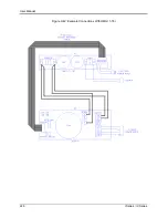
Страница 240: ...User Manual 226 i Series iX Series Figure 9 42 Example Connections With OMNI 1 18i...
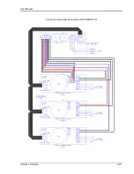
Страница 241: ...User Manual i Series iX Series 227 Figure 9 43 Example Connections With OMNI 3 18i...
Страница 242: ...User Manual 228 i Series iX Series Figure 9 44 Schematic Showing OMNI 1 37i and1 37iJ Connected to 5001iX System...
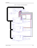
Страница 243: ...User Manual i Series iX Series 229 Figure 9 45 Schematic Showing OMNI 3 37i Connected to 30003iX System...
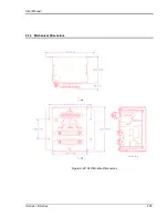
Страница 249: ...User Manual i Series iX Series 235 9 7 4 Mechanical Dimensions Figure 9 49 XLS Module Dimensions...

