

User Manual
i Series / iX Series
121
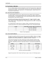
6.6.3 Output Impedance Calibration (3001iX, 5001iX, 9003iX, and 15003iX models only)
For the output impedance calibration, two HP 34401A DMM's or equivalent must be used. The
following modes must be programmed: 6 digits, AC Filter, slow: 3 Hz and 6 digits. One DMM is
used to measure the output voltage, one to measure the load current using a suitable CT. The
calibration should be done for each phase individually. Furthermore, an accurate phase meter
with at least 0.01° resolution is needed. (See equipment list section 6.1). The reference input of
the phase meter must be connected to the LOCK output of the controller at the rear panel of the
master 5001iX chassis. This is a square wave TTL signal. Select Square wave input on the
phase meter. The other input of the phase meter must be connected at the AC source output of
the phase being calibrated. Select Sine wave input on the phase meter for this input. Note that
this is a 230 Vrms signal so the Phase Meter must have sufficient input range on this input. The
phase meter is used to determine the phase shift between no load and full load conditions (
).
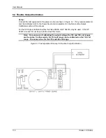
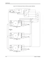
Connect the test equipment required as shown in Figure 6-2. If the DMM and phase meter have
an IEEE/GPIB interface, it is possible to use the 16-bit version of the CIGUI program version 3.18
or higher supplied on the CD ROM that came with the iX Series to operate the test equipment.
The 16-bit CIGUI requires a Windows 98 PC. (This function is not included in the 32 bit Cigui32
program however).
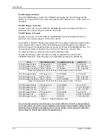
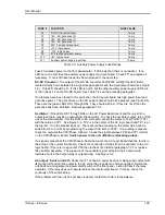
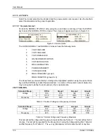
The calibration for impedance can be found in the Calibration Menu on the main CIGUI screen.
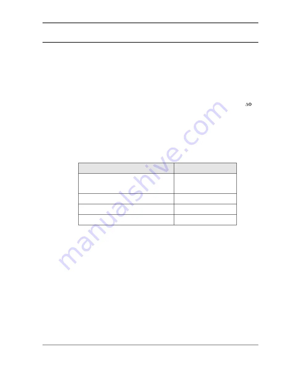
In this case, the GPIB interface must be connected to the PC, the DMM's and the Phase meter.
The GPIB addresses for the DMM's and Phase meter expected by the CIGUI program are
shown in the table below.
Instrument
Address
iX AC Power Source
(Do not use 4,5 or 6 for AC source)
Set in CIGUI Interface screen
and Utility Menu on iX
controller.
DMM1, Used for voltage measurement
4
DMM2, Used for current measurement
5
Phase Meter, Used for phase measurement
6
Table 6-6: GPIB addresses for impedance calibration
Note that the CIGUI32 (32 bit version) does not support computer aided impedance calibration.
Instead, the readings from the DMM's and Phase meter can be made manually and written
down. In that case, a calculator may be used to calculate the R and L portions of the impedance
using the formulas shown in Table 6-8.
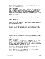
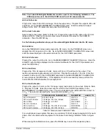
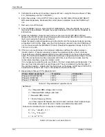
To verify or adjust the programmable impedance function, proceed as follows for each phase:
1. Program the power source to 230.0VAC and 50Hz.
2. Program the output impedance resistance and inductance to the lowest values from the
OUTPUT IMPEDANCE screen. This will be the IMP. REAL MIN and IMP. REACT MIN
values that have been set in the OUTPUT CAL screen. Press the PHASE key to select the
phase to be calibrated. (A, B or C).
3. Measure the output voltage of the power source with no load and record this value (V
NL
).
4. Using a resistive load bank, load the output of the power source to about 16 amps. Measure
the output voltage of the power source under load and record this value (V
L
). Also measure
the load current and record this value. (I).
Содержание 10001i
Страница 2: ......
Страница 3: ......
Страница 6: ...ii This page intentionally left blank...
Страница 25: ...User Manual i Series iX Series 11 Parameter Specification Shock Designed to meet NSTA 1A transportation levels...
Страница 38: ...User Manual 24 i Series iX Series Figure 3 5 Rear Panel View for the 3001i 3001iX...
Страница 39: ...User Manual i Series iX Series 25 Figure 3 6 Rear Panel View for the 5001i 5001iX...
Страница 42: ...User Manual 28 i Series iX Series Figure 3 7 Connection For Single Power Source 5001iX i 3001iX i...
Страница 43: ...User Manual i Series iX Series 29 Figure 3 8 Functional Test Setup...
Страница 44: ...User Manual 30 i Series iX Series Figure 3 9 Single Phase 10000 VA System 10001iX i...
Страница 45: ...User Manual i Series iX Series 31 Figure 3 10 Three Phase 15000 VA System 15003iX i LK Three Controllers...
Страница 46: ...User Manual 32 i Series iX Series Figure 3 11 Single Phase 15000 VA System 15001iX i...
Страница 47: ...User Manual i Series iX Series 33 Figure 3 12 Three Phase 15000 VA system 15003iX i One Controller...
Страница 48: ...User Manual 34 i Series iX Series Figure 3 13 Connection With MODE Option...
Страница 49: ...User Manual i Series iX Series 35 Figure 3 14 Two Phase 10000 VA System 10002i LK Two Controllers...
Страница 50: ...User Manual 36 i Series iX Series Figure 3 15 Three Phase 9000 VA System 9003iX i One Controller...
Страница 118: ...User Manual 104 i Series iX Series Figure 5 2 Power Source Module Block Diagram...
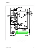
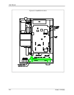
Страница 121: ...User Manual i Series iX Series 107 Figure 5 3 5001i Internal Layout...
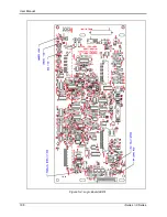
Страница 122: ...User Manual 108 i Series iX Series Figure 5 4 Logic Board LED s...
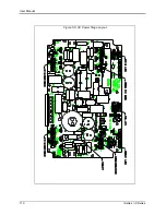
Страница 124: ...User Manual 110 i Series iX Series Figure 5 5 AC Power Stage Layout...
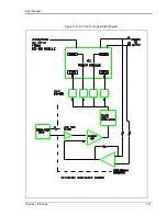
Страница 125: ...User Manual i Series iX Series 111 Figure 5 6 AC Control Logic Block Diagram...
Страница 132: ...User Manual 118 i Series iX Series Figure 6 2 Test Equipment Hook up for Measurement Calibration...
Страница 138: ...User Manual 124 i Series iX Series Figure 6 3 Adjustment Location...
Страница 152: ...User Manual 138 i Series iX Series Figure 9 4 Voltage Modulation...
Страница 219: ...User Manual i Series iX Series 205 Figure 9 36 Example Connection With 5001iX and EOS 1...
Страница 220: ...User Manual 206 i Series iX Series Figure 9 37 Example Connection With Compliance Test System and EOS 1...
Страница 221: ...User Manual i Series iX Series 207 Figure 9 38 15003iX CTS EOS3 LR3...
Страница 222: ...User Manual 208 i Series iX Series Figure 9 39 15003iX 3 EOS3...
Страница 226: ...User Manual 212 i Series iX Series Figure 9 40 EOS3 Location of 70 80 Taps for each phase Lug 3 70 Lug 5 80...
Страница 233: ...User Manual i Series iX Series 219 Figure 9 41 Example Connection With MODE iX...
Страница 240: ...User Manual 226 i Series iX Series Figure 9 42 Example Connections With OMNI 1 18i...
Страница 241: ...User Manual i Series iX Series 227 Figure 9 43 Example Connections With OMNI 3 18i...
Страница 242: ...User Manual 228 i Series iX Series Figure 9 44 Schematic Showing OMNI 1 37i and1 37iJ Connected to 5001iX System...
Страница 243: ...User Manual i Series iX Series 229 Figure 9 45 Schematic Showing OMNI 3 37i Connected to 30003iX System...
Страница 249: ...User Manual i Series iX Series 235 9 7 4 Mechanical Dimensions Figure 9 49 XLS Module Dimensions...