


User Manual
12
i Series / iX Series
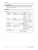
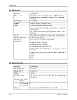
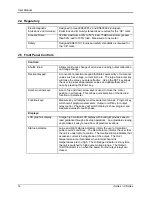
2.4 Regulatory
Electromagnetic
Emissions and Immunity:
Designed to meet EN50081-2 and EN50082-2 European
Emissions and Immunity standard
s as required for the “CE” mark.
Acoustic Noise:
65 dBA maximum at 0% to 50% load, 75 dBA maximum greater
than 50% load to 100% load. Measured at one meter.
Safety:
Designed EN61010-1 European safety standards as required for
the “CE” mark.
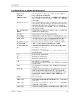
2.5 Front Panel Controls
Controls:
Shuttle knob:
Allows continuous change of all values including output calibration
and range change.
Decimal keypad:
A conventional decimal keypad facilitates quick entry of numerical
values such as voltage, current limit, etc. The large blue enter key
will make the value you enter effective. Using the SET key allows
the user to preset all parameter values and update them all at
once by pressing the Enter key.
Up/down arrow keys:
A set of up and down arrow keys is used to move the cursor
position in all menus. This allows quick selection of the desired
function or parameter.
Function keys:
Measure key will display most measurement values. Program key
will show all program parameters. Output on/off key for output
relay control. Phase key will switch display to show program and
measured values for each phase.
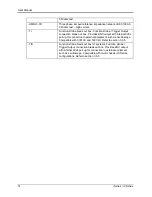
Displays:
LCD graphics display:
A large high contrast LCD display with backlight provides easy to
read guidance through all setup operations. An adjustable viewing
angle makes it easy to read from all practical locations.
Status indicators:
Large and bright status indicators inform the user of important
power source conditions. The Remote lamp informs the user that
the unit is under remote control. The Overload lamp indicates that
excessive current is being drawn at the output. The Over
temperature lamp illuminates when internal heat sink
temperatures are too high. The Hi Range indicator is lit any time
the unit is switched to high output voltage range. The Output
On/Off indicator is on when the power source output relays are
closed.
Содержание 10001i
Страница 2: ......
Страница 3: ......
Страница 6: ...ii This page intentionally left blank...
Страница 25: ...User Manual i Series iX Series 11 Parameter Specification Shock Designed to meet NSTA 1A transportation levels...
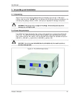
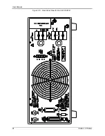
Страница 38: ...User Manual 24 i Series iX Series Figure 3 5 Rear Panel View for the 3001i 3001iX...
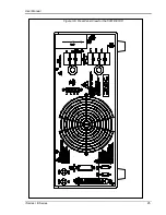
Страница 39: ...User Manual i Series iX Series 25 Figure 3 6 Rear Panel View for the 5001i 5001iX...
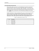
Страница 42: ...User Manual 28 i Series iX Series Figure 3 7 Connection For Single Power Source 5001iX i 3001iX i...
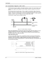
Страница 43: ...User Manual i Series iX Series 29 Figure 3 8 Functional Test Setup...
Страница 44: ...User Manual 30 i Series iX Series Figure 3 9 Single Phase 10000 VA System 10001iX i...
Страница 45: ...User Manual i Series iX Series 31 Figure 3 10 Three Phase 15000 VA System 15003iX i LK Three Controllers...
Страница 46: ...User Manual 32 i Series iX Series Figure 3 11 Single Phase 15000 VA System 15001iX i...
Страница 47: ...User Manual i Series iX Series 33 Figure 3 12 Three Phase 15000 VA system 15003iX i One Controller...
Страница 48: ...User Manual 34 i Series iX Series Figure 3 13 Connection With MODE Option...
Страница 49: ...User Manual i Series iX Series 35 Figure 3 14 Two Phase 10000 VA System 10002i LK Two Controllers...
Страница 50: ...User Manual 36 i Series iX Series Figure 3 15 Three Phase 9000 VA System 9003iX i One Controller...
Страница 118: ...User Manual 104 i Series iX Series Figure 5 2 Power Source Module Block Diagram...
Страница 121: ...User Manual i Series iX Series 107 Figure 5 3 5001i Internal Layout...
Страница 122: ...User Manual 108 i Series iX Series Figure 5 4 Logic Board LED s...
Страница 124: ...User Manual 110 i Series iX Series Figure 5 5 AC Power Stage Layout...
Страница 125: ...User Manual i Series iX Series 111 Figure 5 6 AC Control Logic Block Diagram...
Страница 132: ...User Manual 118 i Series iX Series Figure 6 2 Test Equipment Hook up for Measurement Calibration...
Страница 138: ...User Manual 124 i Series iX Series Figure 6 3 Adjustment Location...
Страница 152: ...User Manual 138 i Series iX Series Figure 9 4 Voltage Modulation...
Страница 219: ...User Manual i Series iX Series 205 Figure 9 36 Example Connection With 5001iX and EOS 1...
Страница 220: ...User Manual 206 i Series iX Series Figure 9 37 Example Connection With Compliance Test System and EOS 1...
Страница 221: ...User Manual i Series iX Series 207 Figure 9 38 15003iX CTS EOS3 LR3...
Страница 222: ...User Manual 208 i Series iX Series Figure 9 39 15003iX 3 EOS3...
Страница 226: ...User Manual 212 i Series iX Series Figure 9 40 EOS3 Location of 70 80 Taps for each phase Lug 3 70 Lug 5 80...
Страница 233: ...User Manual i Series iX Series 219 Figure 9 41 Example Connection With MODE iX...
Страница 240: ...User Manual 226 i Series iX Series Figure 9 42 Example Connections With OMNI 1 18i...
Страница 241: ...User Manual i Series iX Series 227 Figure 9 43 Example Connections With OMNI 3 18i...
Страница 242: ...User Manual 228 i Series iX Series Figure 9 44 Schematic Showing OMNI 1 37i and1 37iJ Connected to 5001iX System...
Страница 243: ...User Manual i Series iX Series 229 Figure 9 45 Schematic Showing OMNI 3 37i Connected to 30003iX System...
Страница 249: ...User Manual i Series iX Series 235 9 7 4 Mechanical Dimensions Figure 9 49 XLS Module Dimensions...