User Manual
60
i Series / iX Series
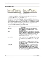
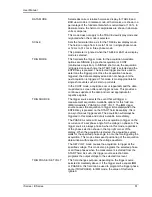
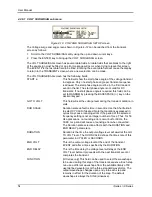
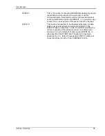
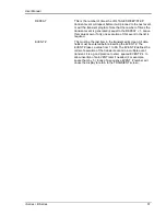
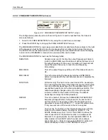
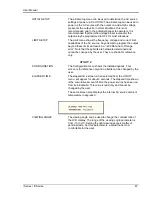
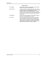
EVENT #
This must be the last item in the transient edit screen. All data
fields must be entered before inserting the EVENT #. The
EVENT # takes value from 1 to 99. The EVENT # defines the
order of execution of the transient events in a multiple event
transient. It is a good practice to enter spaced EVENT #‟s to
allow insertion of an EVENT later if needed. (For example,
space them by 5.) Entry of a sequence EVENT # number will
cause the display to return to the TRANSIENT screen.
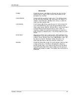
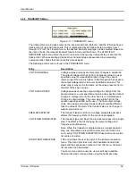
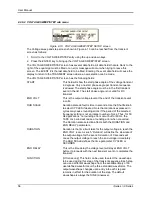
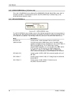
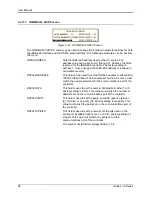
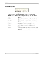
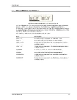
4.2.6.5 START/VIEW TRANSIENT SEQUENCE sub menu
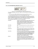
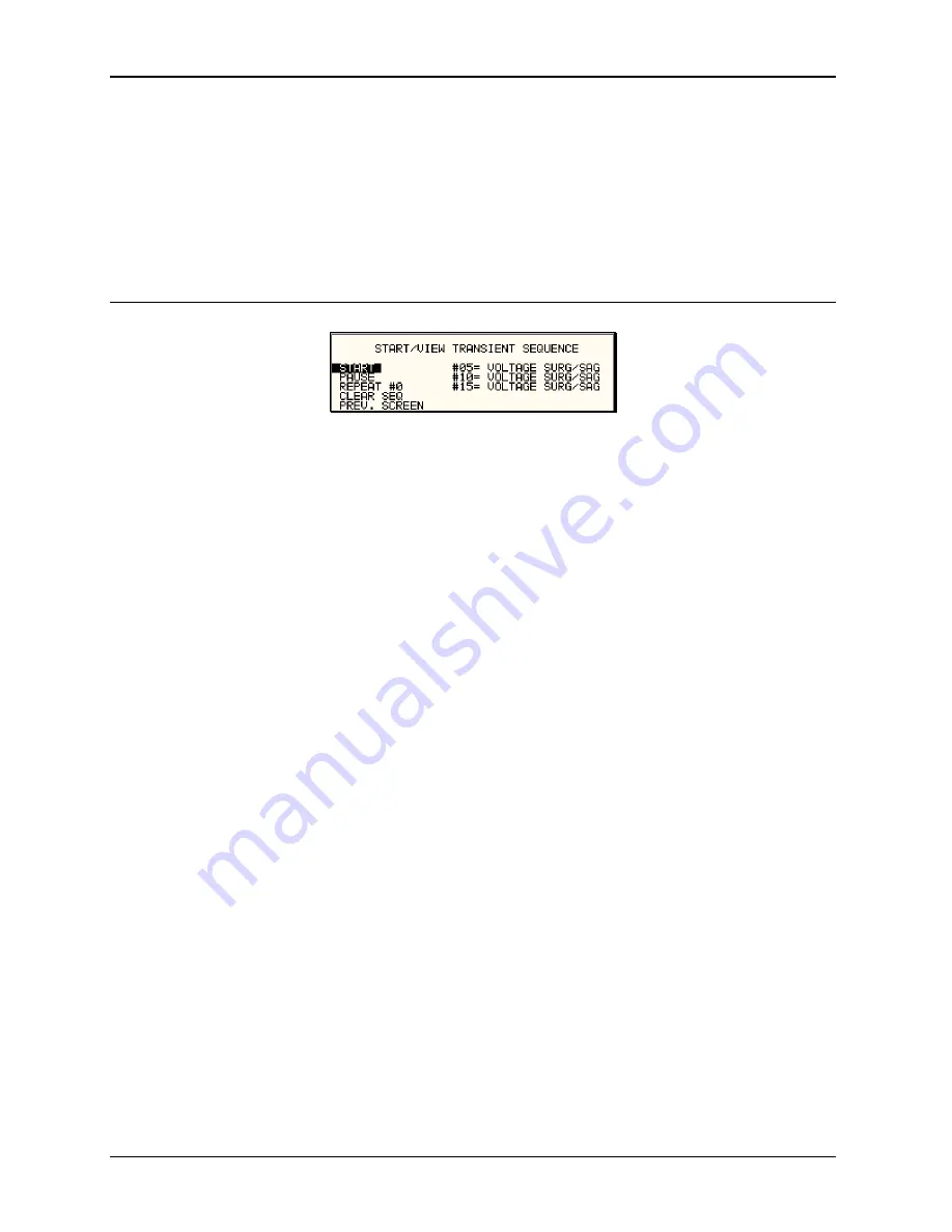
Figure 4-16: START/VIEW TRANSIENT SEQUENCE screen
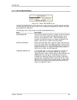
The START/VIEW TRANSIENT SEQUENCE screen is used to control transient execution. It
also provides an overview of available transient list events. This list appears in the order they
were assigned event numbers. Editing an existing event can be accomplished from this screen
by positioning the cursor on the event to be edited and pressing the ENTER key. This method
can also be used to review the parameters of a previously entered event.
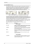
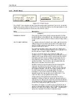
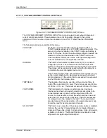
The START/VIEW TRANSIENT SEQUENCE screen has the following fields:
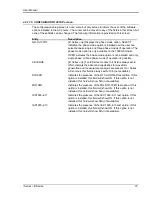
START / ABORT
The START field is used to start a transient execution. When
the cursor is positioned on the START field and the ENTER key
is pressed, transient execution starts. The output relay must be
closed or an error message will appear and the transient will not
start.
Once a transient is in progress, this field changes to ABORT
and can be used to abort a transient in progress. If the transient
completes execution, the field reverts back to START.
PAUSE / RESUME
The PAUSE field may be used to suspend execution of a
transient list in progress. If the cursor is on the PAUSE field and
the ENTER key is pressed, the transient is suspended and this
field changes to RESUME. Pressing the ENTER key again will
cause the transient list to resume execution from the point
where it was suspended.
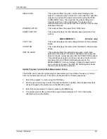
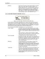
REPEAT #
This field determines the number of times a transient list is
repeated. The default value is zero which means the
programmed list runs only once. The range for this field is from
0 through 99999. This repeat function should not be confused
with the REPEAT function available for individual events. The
event specific repeat value will cause only that event to be
repeated, not the entire list.
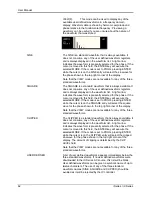
CLEAR SEQ
Moving the cursor to this field and pressing the ENTER key will
cause the entire programmed transient list to be erased. Be
careful not to press ENTER accidentally while on this field as
you will loose the programmed transient list. Note that a list may
be stored as part of the front panel setup in the nonvolatile
memory registers.
Содержание 10001i
Страница 2: ......
Страница 3: ......
Страница 6: ...ii This page intentionally left blank...
Страница 25: ...User Manual i Series iX Series 11 Parameter Specification Shock Designed to meet NSTA 1A transportation levels...
Страница 38: ...User Manual 24 i Series iX Series Figure 3 5 Rear Panel View for the 3001i 3001iX...
Страница 39: ...User Manual i Series iX Series 25 Figure 3 6 Rear Panel View for the 5001i 5001iX...
Страница 42: ...User Manual 28 i Series iX Series Figure 3 7 Connection For Single Power Source 5001iX i 3001iX i...
Страница 43: ...User Manual i Series iX Series 29 Figure 3 8 Functional Test Setup...
Страница 44: ...User Manual 30 i Series iX Series Figure 3 9 Single Phase 10000 VA System 10001iX i...
Страница 45: ...User Manual i Series iX Series 31 Figure 3 10 Three Phase 15000 VA System 15003iX i LK Three Controllers...
Страница 46: ...User Manual 32 i Series iX Series Figure 3 11 Single Phase 15000 VA System 15001iX i...
Страница 47: ...User Manual i Series iX Series 33 Figure 3 12 Three Phase 15000 VA system 15003iX i One Controller...
Страница 48: ...User Manual 34 i Series iX Series Figure 3 13 Connection With MODE Option...
Страница 49: ...User Manual i Series iX Series 35 Figure 3 14 Two Phase 10000 VA System 10002i LK Two Controllers...
Страница 50: ...User Manual 36 i Series iX Series Figure 3 15 Three Phase 9000 VA System 9003iX i One Controller...
Страница 118: ...User Manual 104 i Series iX Series Figure 5 2 Power Source Module Block Diagram...
Страница 121: ...User Manual i Series iX Series 107 Figure 5 3 5001i Internal Layout...
Страница 122: ...User Manual 108 i Series iX Series Figure 5 4 Logic Board LED s...
Страница 124: ...User Manual 110 i Series iX Series Figure 5 5 AC Power Stage Layout...
Страница 125: ...User Manual i Series iX Series 111 Figure 5 6 AC Control Logic Block Diagram...
Страница 132: ...User Manual 118 i Series iX Series Figure 6 2 Test Equipment Hook up for Measurement Calibration...
Страница 138: ...User Manual 124 i Series iX Series Figure 6 3 Adjustment Location...
Страница 152: ...User Manual 138 i Series iX Series Figure 9 4 Voltage Modulation...
Страница 219: ...User Manual i Series iX Series 205 Figure 9 36 Example Connection With 5001iX and EOS 1...
Страница 220: ...User Manual 206 i Series iX Series Figure 9 37 Example Connection With Compliance Test System and EOS 1...
Страница 221: ...User Manual i Series iX Series 207 Figure 9 38 15003iX CTS EOS3 LR3...
Страница 222: ...User Manual 208 i Series iX Series Figure 9 39 15003iX 3 EOS3...
Страница 226: ...User Manual 212 i Series iX Series Figure 9 40 EOS3 Location of 70 80 Taps for each phase Lug 3 70 Lug 5 80...
Страница 233: ...User Manual i Series iX Series 219 Figure 9 41 Example Connection With MODE iX...
Страница 240: ...User Manual 226 i Series iX Series Figure 9 42 Example Connections With OMNI 1 18i...
Страница 241: ...User Manual i Series iX Series 227 Figure 9 43 Example Connections With OMNI 3 18i...
Страница 242: ...User Manual 228 i Series iX Series Figure 9 44 Schematic Showing OMNI 1 37i and1 37iJ Connected to 5001iX System...
Страница 243: ...User Manual i Series iX Series 229 Figure 9 45 Schematic Showing OMNI 3 37i Connected to 30003iX System...
Страница 249: ...User Manual i Series iX Series 235 9 7 4 Mechanical Dimensions Figure 9 49 XLS Module Dimensions...

