


User Manual
230
i Series / iX Series
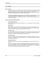
9.6.6 Operation
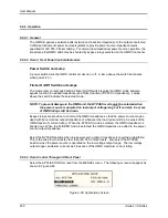
9.6.6.1 General
The OMNI impedance network adds resistive and inductive impedance to the output of selected
California Instruments power sources/systems to provide power source impedance levels
specified for IEC 555-3 flicker testing. For normal (low impedance) power source operation, the
impedance that OMNI adds may be shunted by bypass relays selected on the OMNI front panel.
9.6.6.2 Omni i Front Panel Controls/Indicators
Power Switch and Lamp
A power switch turns the OMNI control circuits on or off. A lamp above the switch illuminates
when power is on.
Flicker On/Off Switch and Lamps
The momentary contact push button Flicker On/Off switch toggles the OMNI mode between
bypass function (no added impedance) and flicker function (IEC 555-3 impedance). Lamps
above the switch indicate the selected mode.
NOTE: To prevent damage to the OMNI unit, the BYPASS mode must be selected when
the power source is operated on low output voltage range or if currents in excess
of OMNI ratings will be drawn.
Bypass relays are provided to short out the OMNI impedance so that the power source may be
used with its normal low output impedance or whenever the load current will be in excess of the
OMNI maximum current rating. When the BYPASS mode is selected, the OMNI impedance is
shorted out. When the FLICKER mode is selected, the OMNI impedance is added to the power
source output impedance.
Select the BYPASS position when low power source output impedance is required or desirable.
This is the case for most tests other than IEC 555-3 flicker tests. Also select the BYPASS
position when the power source is operated on the low voltage output range. The low voltage
output range can deliver currents well in excess of the OMNI maximum current rating.
9.6.6.3 Omni Control Through i/iX Front Panel
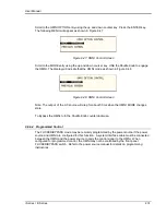
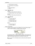
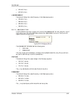
Select the APPLICATIONS screen from the MENU2 screen. The following screen will appear as
shown in Figure 9-46
Figure 9-46: Applications Screen
Содержание 10001i
Страница 2: ......
Страница 3: ......
Страница 6: ...ii This page intentionally left blank...
Страница 25: ...User Manual i Series iX Series 11 Parameter Specification Shock Designed to meet NSTA 1A transportation levels...
Страница 38: ...User Manual 24 i Series iX Series Figure 3 5 Rear Panel View for the 3001i 3001iX...
Страница 39: ...User Manual i Series iX Series 25 Figure 3 6 Rear Panel View for the 5001i 5001iX...
Страница 42: ...User Manual 28 i Series iX Series Figure 3 7 Connection For Single Power Source 5001iX i 3001iX i...
Страница 43: ...User Manual i Series iX Series 29 Figure 3 8 Functional Test Setup...
Страница 44: ...User Manual 30 i Series iX Series Figure 3 9 Single Phase 10000 VA System 10001iX i...
Страница 45: ...User Manual i Series iX Series 31 Figure 3 10 Three Phase 15000 VA System 15003iX i LK Three Controllers...
Страница 46: ...User Manual 32 i Series iX Series Figure 3 11 Single Phase 15000 VA System 15001iX i...
Страница 47: ...User Manual i Series iX Series 33 Figure 3 12 Three Phase 15000 VA system 15003iX i One Controller...
Страница 48: ...User Manual 34 i Series iX Series Figure 3 13 Connection With MODE Option...
Страница 49: ...User Manual i Series iX Series 35 Figure 3 14 Two Phase 10000 VA System 10002i LK Two Controllers...
Страница 50: ...User Manual 36 i Series iX Series Figure 3 15 Three Phase 9000 VA System 9003iX i One Controller...
Страница 118: ...User Manual 104 i Series iX Series Figure 5 2 Power Source Module Block Diagram...
Страница 121: ...User Manual i Series iX Series 107 Figure 5 3 5001i Internal Layout...
Страница 122: ...User Manual 108 i Series iX Series Figure 5 4 Logic Board LED s...
Страница 124: ...User Manual 110 i Series iX Series Figure 5 5 AC Power Stage Layout...
Страница 125: ...User Manual i Series iX Series 111 Figure 5 6 AC Control Logic Block Diagram...
Страница 132: ...User Manual 118 i Series iX Series Figure 6 2 Test Equipment Hook up for Measurement Calibration...
Страница 138: ...User Manual 124 i Series iX Series Figure 6 3 Adjustment Location...
Страница 152: ...User Manual 138 i Series iX Series Figure 9 4 Voltage Modulation...
Страница 219: ...User Manual i Series iX Series 205 Figure 9 36 Example Connection With 5001iX and EOS 1...
Страница 220: ...User Manual 206 i Series iX Series Figure 9 37 Example Connection With Compliance Test System and EOS 1...
Страница 221: ...User Manual i Series iX Series 207 Figure 9 38 15003iX CTS EOS3 LR3...
Страница 222: ...User Manual 208 i Series iX Series Figure 9 39 15003iX 3 EOS3...
Страница 226: ...User Manual 212 i Series iX Series Figure 9 40 EOS3 Location of 70 80 Taps for each phase Lug 3 70 Lug 5 80...
Страница 233: ...User Manual i Series iX Series 219 Figure 9 41 Example Connection With MODE iX...
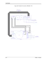
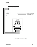
Страница 240: ...User Manual 226 i Series iX Series Figure 9 42 Example Connections With OMNI 1 18i...
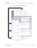
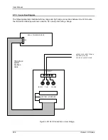
Страница 241: ...User Manual i Series iX Series 227 Figure 9 43 Example Connections With OMNI 3 18i...
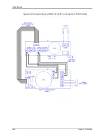
Страница 242: ...User Manual 228 i Series iX Series Figure 9 44 Schematic Showing OMNI 1 37i and1 37iJ Connected to 5001iX System...
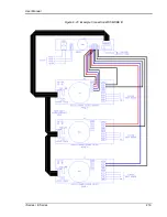
Страница 243: ...User Manual i Series iX Series 229 Figure 9 45 Schematic Showing OMNI 3 37i Connected to 30003iX System...
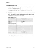
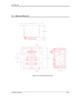
Страница 249: ...User Manual i Series iX Series 235 9 7 4 Mechanical Dimensions Figure 9 49 XLS Module Dimensions...