


User Manual
i Series / iX Series
321
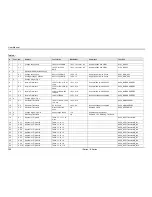
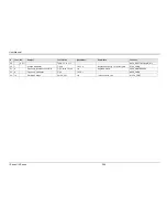
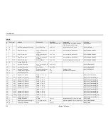
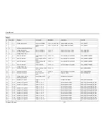
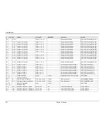
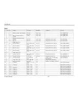
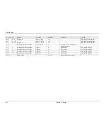
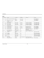
Number
Message String
Cause
Remedy
allowed"
correct command syntax
-200
"Execution error"
Command could not
be executed
Command may be inconsistent with
mode of operation such as
programming frequency when in DC
mode.
-201
"Invalid while in local"
Command issued but
unit is not in remote
state
Put instrument in remote state before
issuing GPIB commands.
-203
"Command protected"
Command is locked
out
Some commands are supported by
the unit but are locked out for
protection of settings and are not
user accessible.
-210
"Trigger error"
Problem with trigger
system.
Unit could not generate trigger for
transient execution or measurement.
-211
"Trigger ignored"
Trigger request has
been ignored.
Trigger setup incorrect or unit was not
armed when trigger was received.
Check transient system or
measurement trigger system settings.
-213
"Init ignored"
Initialization request
has been ignored
Unit was told to go to armed state but
was unable to do so. Could be
caused by incorrect transient system
or measurement acquisition setup.
-220
"Parameter error"
Parameter not
allowed.
Incorrect parameter or parameter
value. Check programming manual
for allowable parameters
-221
"Setting conflict"
Requested setting
conflicts with other
setting in effect.
Check other settings. E.g. trying to
program a DC offset while in AC
mode
-222
"Data out of range"
Parameter data
outside of allowable
range.
Check programming manual for
allowable parameter values
-223
"Too much data"
More data received
than expected
Check programming manual for
number of parameters or data block
size
-224
"Illegal parameter
value"
Parameter value is
not suppored
Check programming manual for
correct parameters
-226
"Lists not same length" One or more
transient lists
programmed has
different length.
All lists must be of same length or
transient cannot be compiled and
executed.
-241
"Hardware missing"
N/A
N/A
-254
"Media full"
No storage space left
to save settings or
data.
Delete other settings or data to make
room.
-255
“Directory full”
Too many waveform
directory entries
Delete one or more waveforms from
waveform memory to make room.
-256
“File name not found”
Waveform requested
not in directory
Check waveform directory for
waveform names present.
-257
“File name error”
Incorrect filename
Too many or non ASCII characters
used in waveform file definition.
-283
“Illegal variable name”
Variable name illegal.
Use ASCII characters only
-300
"Device specific error"
Hardware related
Check hardware for proper operation.
Содержание 10001i
Страница 2: ......
Страница 3: ......
Страница 6: ...ii This page intentionally left blank...
Страница 25: ...User Manual i Series iX Series 11 Parameter Specification Shock Designed to meet NSTA 1A transportation levels...
Страница 38: ...User Manual 24 i Series iX Series Figure 3 5 Rear Panel View for the 3001i 3001iX...
Страница 39: ...User Manual i Series iX Series 25 Figure 3 6 Rear Panel View for the 5001i 5001iX...
Страница 42: ...User Manual 28 i Series iX Series Figure 3 7 Connection For Single Power Source 5001iX i 3001iX i...
Страница 43: ...User Manual i Series iX Series 29 Figure 3 8 Functional Test Setup...
Страница 44: ...User Manual 30 i Series iX Series Figure 3 9 Single Phase 10000 VA System 10001iX i...
Страница 45: ...User Manual i Series iX Series 31 Figure 3 10 Three Phase 15000 VA System 15003iX i LK Three Controllers...
Страница 46: ...User Manual 32 i Series iX Series Figure 3 11 Single Phase 15000 VA System 15001iX i...
Страница 47: ...User Manual i Series iX Series 33 Figure 3 12 Three Phase 15000 VA system 15003iX i One Controller...
Страница 48: ...User Manual 34 i Series iX Series Figure 3 13 Connection With MODE Option...
Страница 49: ...User Manual i Series iX Series 35 Figure 3 14 Two Phase 10000 VA System 10002i LK Two Controllers...
Страница 50: ...User Manual 36 i Series iX Series Figure 3 15 Three Phase 9000 VA System 9003iX i One Controller...
Страница 118: ...User Manual 104 i Series iX Series Figure 5 2 Power Source Module Block Diagram...
Страница 121: ...User Manual i Series iX Series 107 Figure 5 3 5001i Internal Layout...
Страница 122: ...User Manual 108 i Series iX Series Figure 5 4 Logic Board LED s...
Страница 124: ...User Manual 110 i Series iX Series Figure 5 5 AC Power Stage Layout...
Страница 125: ...User Manual i Series iX Series 111 Figure 5 6 AC Control Logic Block Diagram...
Страница 132: ...User Manual 118 i Series iX Series Figure 6 2 Test Equipment Hook up for Measurement Calibration...
Страница 138: ...User Manual 124 i Series iX Series Figure 6 3 Adjustment Location...
Страница 152: ...User Manual 138 i Series iX Series Figure 9 4 Voltage Modulation...
Страница 219: ...User Manual i Series iX Series 205 Figure 9 36 Example Connection With 5001iX and EOS 1...
Страница 220: ...User Manual 206 i Series iX Series Figure 9 37 Example Connection With Compliance Test System and EOS 1...
Страница 221: ...User Manual i Series iX Series 207 Figure 9 38 15003iX CTS EOS3 LR3...
Страница 222: ...User Manual 208 i Series iX Series Figure 9 39 15003iX 3 EOS3...
Страница 226: ...User Manual 212 i Series iX Series Figure 9 40 EOS3 Location of 70 80 Taps for each phase Lug 3 70 Lug 5 80...
Страница 233: ...User Manual i Series iX Series 219 Figure 9 41 Example Connection With MODE iX...
Страница 240: ...User Manual 226 i Series iX Series Figure 9 42 Example Connections With OMNI 1 18i...
Страница 241: ...User Manual i Series iX Series 227 Figure 9 43 Example Connections With OMNI 3 18i...
Страница 242: ...User Manual 228 i Series iX Series Figure 9 44 Schematic Showing OMNI 1 37i and1 37iJ Connected to 5001iX System...
Страница 243: ...User Manual i Series iX Series 229 Figure 9 45 Schematic Showing OMNI 3 37i Connected to 30003iX System...
Страница 249: ...User Manual i Series iX Series 235 9 7 4 Mechanical Dimensions Figure 9 49 XLS Module Dimensions...