User Manual
i Series / iX Series
137
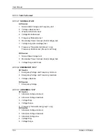
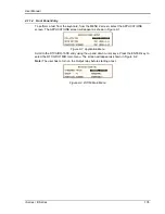
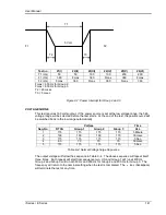
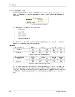
VOLT FREQ MAX
This test will set the voltage and frequency to levels defined by Table 9-2. The test will last for 30
minutes. The test will be repeated for the EURO standard using the Voltage setting from
Table 9-1 and the frequency from Table 9-2. The CLR Key in local operation will terminate the test
at any time. Group execute trigger will terminate the test remotely. The unselected phases will
remain at 115 volts. The
key (backspace) will terminate the test at any time.
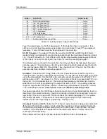
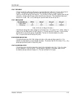
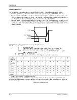
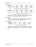
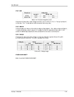
VOLT UNBALANCE
Standard/Group
RTCA
Group1
Group2
Group3
Voltage offset
6
6
6
9
Frequency
400
400
360/650
360/800
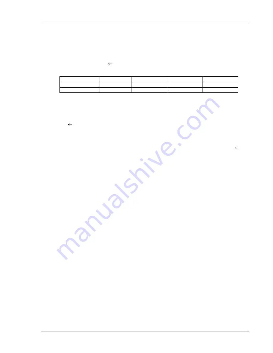
Table 9-3: Normal Voltage Unbalance
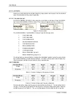
This test will change the output voltage for each phase from 115 volts to 115V + offset. Refer to
Table 9-3 for the offset value and the Frequency. The test will last 30 minutes. The test will be
repeated for a second Frequency if applicable. The test can be terminated at any time.
The
key will terminate the test at any time.
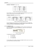
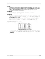
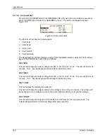
WAVEFORM DISTORTION
This test will generate a 5% THD voltage distortion on the output voltage waveform. The
distortion is generated by using a clipped sinewave. The test will last for 30 minutes. The
key
(backspace) will terminate the test at any time.
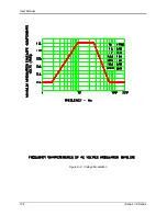
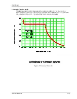
VOLTAGE MODULATION
This test requires a numeric value entry equal to the modulation rate in Hz. This entry value
must be between 1 Hz and 200 Hz. The amplitude modulation is calculated based on the
modulation rate as defined in Figure 9-4. This test will last for 2 minutes.
Содержание 10001i
Страница 2: ......
Страница 3: ......
Страница 6: ...ii This page intentionally left blank...
Страница 25: ...User Manual i Series iX Series 11 Parameter Specification Shock Designed to meet NSTA 1A transportation levels...
Страница 38: ...User Manual 24 i Series iX Series Figure 3 5 Rear Panel View for the 3001i 3001iX...
Страница 39: ...User Manual i Series iX Series 25 Figure 3 6 Rear Panel View for the 5001i 5001iX...
Страница 42: ...User Manual 28 i Series iX Series Figure 3 7 Connection For Single Power Source 5001iX i 3001iX i...
Страница 43: ...User Manual i Series iX Series 29 Figure 3 8 Functional Test Setup...
Страница 44: ...User Manual 30 i Series iX Series Figure 3 9 Single Phase 10000 VA System 10001iX i...
Страница 45: ...User Manual i Series iX Series 31 Figure 3 10 Three Phase 15000 VA System 15003iX i LK Three Controllers...
Страница 46: ...User Manual 32 i Series iX Series Figure 3 11 Single Phase 15000 VA System 15001iX i...
Страница 47: ...User Manual i Series iX Series 33 Figure 3 12 Three Phase 15000 VA system 15003iX i One Controller...
Страница 48: ...User Manual 34 i Series iX Series Figure 3 13 Connection With MODE Option...
Страница 49: ...User Manual i Series iX Series 35 Figure 3 14 Two Phase 10000 VA System 10002i LK Two Controllers...
Страница 50: ...User Manual 36 i Series iX Series Figure 3 15 Three Phase 9000 VA System 9003iX i One Controller...
Страница 118: ...User Manual 104 i Series iX Series Figure 5 2 Power Source Module Block Diagram...
Страница 121: ...User Manual i Series iX Series 107 Figure 5 3 5001i Internal Layout...
Страница 122: ...User Manual 108 i Series iX Series Figure 5 4 Logic Board LED s...
Страница 124: ...User Manual 110 i Series iX Series Figure 5 5 AC Power Stage Layout...
Страница 125: ...User Manual i Series iX Series 111 Figure 5 6 AC Control Logic Block Diagram...
Страница 132: ...User Manual 118 i Series iX Series Figure 6 2 Test Equipment Hook up for Measurement Calibration...
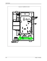
Страница 138: ...User Manual 124 i Series iX Series Figure 6 3 Adjustment Location...
Страница 152: ...User Manual 138 i Series iX Series Figure 9 4 Voltage Modulation...
Страница 219: ...User Manual i Series iX Series 205 Figure 9 36 Example Connection With 5001iX and EOS 1...
Страница 220: ...User Manual 206 i Series iX Series Figure 9 37 Example Connection With Compliance Test System and EOS 1...
Страница 221: ...User Manual i Series iX Series 207 Figure 9 38 15003iX CTS EOS3 LR3...
Страница 222: ...User Manual 208 i Series iX Series Figure 9 39 15003iX 3 EOS3...
Страница 226: ...User Manual 212 i Series iX Series Figure 9 40 EOS3 Location of 70 80 Taps for each phase Lug 3 70 Lug 5 80...
Страница 233: ...User Manual i Series iX Series 219 Figure 9 41 Example Connection With MODE iX...
Страница 240: ...User Manual 226 i Series iX Series Figure 9 42 Example Connections With OMNI 1 18i...
Страница 241: ...User Manual i Series iX Series 227 Figure 9 43 Example Connections With OMNI 3 18i...
Страница 242: ...User Manual 228 i Series iX Series Figure 9 44 Schematic Showing OMNI 1 37i and1 37iJ Connected to 5001iX System...
Страница 243: ...User Manual i Series iX Series 229 Figure 9 45 Schematic Showing OMNI 3 37i Connected to 30003iX System...
Страница 249: ...User Manual i Series iX Series 235 9 7 4 Mechanical Dimensions Figure 9 49 XLS Module Dimensions...


