


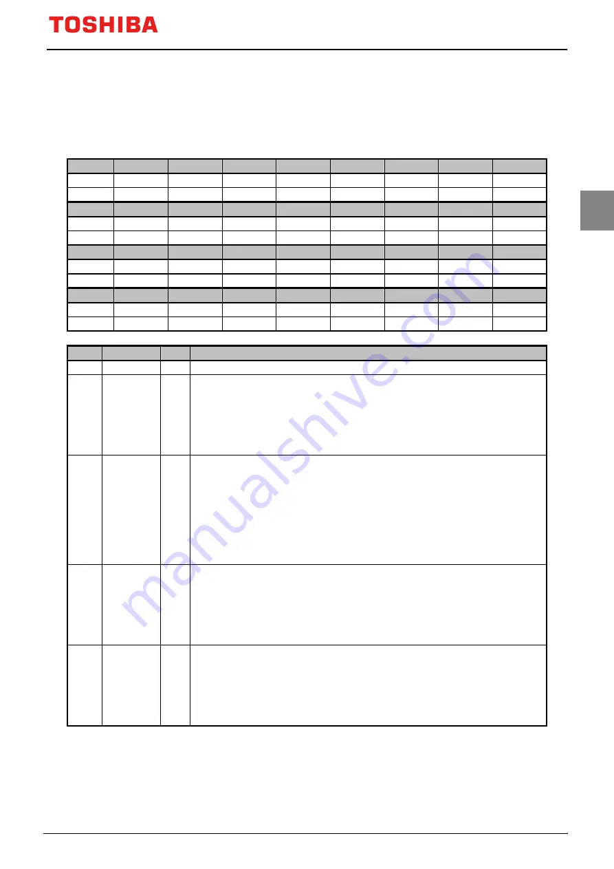
11.3.3 UARTxRSR (Receive Status Register)
Both UARTxRSR and UARTxECR registers are mapped on the same address.
31
30
29
28
27
26
25
24
Bit symbol
-
-
-
-
-
-
-
-
After reset
0
0
0
0
0
0
0
0
23
22
21
20
19
18
17
16
Bit symbol
-
-
-
-
-
-
-
-
After reset
0
0
0
0
0
0
0
0
15
14
13
12
11
10
9
8
Bit symbol
-
-
-
-
-
-
-
-
After reset
0
0
0
0
0
0
0
0
7
6
5
4
3
2
1
0
Bit symbol
-
-
-
-
OE
BE
PE
FE
After reset
0
0
0
0
0
0
0
0
Bit
Bit symbol
Type
Function
31-4
−
R
Read as "0".
3
OE
R
Overrun error
0: No error
1: Error
When data is received, if FIFO has already been full, this bit is set to "1".
This bit is cleared to "0" by writing data to UARTxECR.
If FIFO is full, further data cannot be written. Thus, the content of FIFO is valid and only the content of
shift register is overwritten. CPU must be read data in order to empty FIFO.
2
BE
R
Break error
0: No error
1: Error
If break condition (UTxRXD input is held "Low" for longer than a full-word transmission time defined as
start, data, parity, and stop bits) is detected, this bit is set to "1".
This bit is cleared to "0" by writing data to UARTxECR.
If FIFO is enabled, this error is input to the top of the FIFO. If a break error occurs, "0" is input to FIFO as
data.
In the next data reception, UTxRXD input is set to "1" (marking status), this bit is enabled after a start bit
is received.
1
PE
R
Parity error
0: No error
1: Error
When this bit is "1", this indicates that the parity of received data does not match the parity set in
UARTxLCR_H<EPS> and <SPS>.
This bit is cleared to "0" by writing data to UARTxECR.
If the FIFO is enabled, this error is input to the top of the FIFO.
0
FE
R
Framing error
0: No error
1: Error
When this bit is set to "1", this indicates that a valid stop bit is not included in the received data. (A valid
stop bit length is "1".)
This bit is cleared to "0" by writing data to UARTxECR.
If the FIFO is enabled, this error is input to the top of FIFO.
Note 1: An overrun error is immediately set when the error occurs.
Note 2: UARTxRSR is updated when data is read from UARTxDR. Therefore, received data must be read from
UARTxDR before error status is read from UARTxRSR. This read sequence cannot be reversed. In addition, er-
ror status can be read by reading UARTxDR.
TMPM3V6/M3V4
Page 189
2019-02-06
Summary of Contents for TMPM3V4
Page 1: ...32 Bit RISC Microcontroller TX03 Series TMPM3V6 M3V4 ...
Page 2: ... 2019 Toshiba Electronic Devices Storage Corporation ...
Page 7: ...Revision History Date Revision Comment 2019 02 06 1 First Release ...
Page 8: ......
Page 22: ...xiv ...
Page 52: ...TMPM3V6 M3V4 3 Processor Core 3 6 Exclusive access Page 30 2019 02 06 ...
Page 148: ...TMPM3V6 M3V4 7 Exceptions 7 6 Exception Interrupt Related Registers Page 126 2019 02 06 ...
Page 178: ...TMPM3V6 M3V4 9 Input Output port 9 2 Block Diagrams of Ports Page 156 2019 02 06 ...
Page 354: ...TMPM3V6 M3V4 14 Synchronous Serial Port SSP 14 6 Frame Format Page 332 2019 02 06 ...
Page 419: ...TMPM3V6 M3V4 Page 397 2019 02 06 ...
Page 462: ...TMPM3V6 M3V4 21 Watchdog Timer WDT 21 5 Control register Page 440 2019 02 06 ...
Page 544: ......


