


39
Chapter 3
Using the Control Front Panel
This chapter describes the control front panel, the menus used, and the
functions available for configuring parameters and monitoring
various operational and fault conditions.
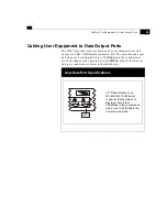
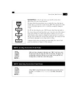
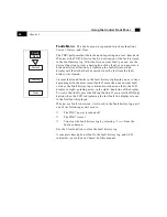
Powering Up
Power– up the unit by pushing the rocker switch on the rear panel
toward the side marked
I
, which is the on position. The LED labeled
Power
on the control front
panel illuminates in green, and
the LCD displays
Initializing
for a few
seconds. After the unit is
initialized, the LCD displays
the first three main menus
beneath the name
MPEG2
Receiver/Decoder
.
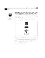
|
0
On/Off
Switch
IRD
MPEG2
Previous
More
Communications
1 2 3
4 5 6
7 8 9
- 0 .
Select
Enter
Select
Select
STATUS FAULT POWER
Previous
More
Communications
1 2 3
4 5 6
7 8 9
- 0 .
Select
Enter
Select
Select
STATUS FAULT POWER
LCD Display
LED Indicators
Summary of Contents for TDR7
Page 17: ...Chapter 1 TDR7 Overview...
Page 18: ......
Page 25: ...Chapter 2 Installing the TDR7...
Page 26: ......
Page 48: ...Chapter 2 34 Installing the TDR7...
Page 49: ...Chapter 3 Using the Control Front Panel...
Page 50: ......
Page 78: ......
Page 79: ...Chapter 4 Using a Remote Control Device Interface...
Page 80: ......
Page 111: ...Chapter 5 Configuring the TDR7...
Page 112: ......
Page 151: ...Chapter 6 Troubleshooting...
Page 152: ......
Page 169: ...157 Appendixes Maintenance Glossary Warranty Specifications and Index...
Page 170: ...I...
Page 176: ...164 Maintenance...


