


129
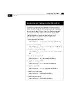
Configuring the TDR7 with a Remote Control Device
Configuring the Demodulator
Once you have finished installing your
TDR7, you must configure the
demodulator to receive the incoming RF signal. To configure the
demodulator, follow the steps below.
Before you begin, you must have the following information:
1.
The incoming signal RF frequency. This frequency may also be
referred to as the satellite downlink frequency. If the frequency is
not in
MHz, convert the frequency to MHz.
2.
The local oscillator frequency of your LNB downconverter. This
frequency is typically posted somewhere on the equipment or in
the manufacturer’s documentation. If the frequency is not in
MHz,
convert the frequency to
MHz.
3.
The transport stream data rate of the incoming RF signal.
4.
The Viterbi code rate of the incoming RF signal.
5.
The polarization of the incoming RF signal.
In this example, assume that you want to configure the
TDR7 to the
following parameters:
•
RF Frequency: 13225
MHz
•
LO Frequency: 11300
MHz
•
Transport Stream Data Rate: 7000000
bps
•
Viterbi Code Rate: 7/8
•
Incoming Signal Polarization: Vertical
Summary of Contents for TDR7
Page 17: ...Chapter 1 TDR7 Overview...
Page 18: ......
Page 25: ...Chapter 2 Installing the TDR7...
Page 26: ......
Page 48: ...Chapter 2 34 Installing the TDR7...
Page 49: ...Chapter 3 Using the Control Front Panel...
Page 50: ......
Page 78: ......
Page 79: ...Chapter 4 Using a Remote Control Device Interface...
Page 80: ......
Page 111: ...Chapter 5 Configuring the TDR7...
Page 112: ......
Page 151: ...Chapter 6 Troubleshooting...
Page 152: ......
Page 169: ...157 Appendixes Maintenance Glossary Warranty Specifications and Index...
Page 170: ...I...
Page 176: ...164 Maintenance...


