1D-26 Engine Mechanical:
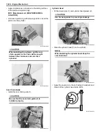
• Align the marks “C” on the camshaft so that they are
parallel with the surface of the cylinder head.
• Engage the hole of the camshaft sprocket with the
locating pin (4) on the camshaft.
NOTE
Do not rotate the crankshaft while installing
the camshaft or cam chain.
• Install the lock washer (5) so that it is covering the
locating pin (4).
CAUTION
!
Replace the lock washer (4) with a new one.
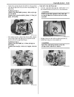
• Apply a small quantity of thread lock to the camshaft
sprocket bolts and tighten them to the specified
torque.
: Thread lock cement 99000–32030
(THREAD LOCK CEMENT SUPER 1303 or
equivalent)
Tightening torque
Camshaft sprocket bolt (a): 15 N·m (1.5 kgf-m,
11.0 lbf-ft)
• Bend up the washer tongue positively to lock the
bolts.
• Apply molybdenum oil solution to the cam faces and
journals.
M/O: Molybdenum oil (MOLYBDENUM OIL
SOLUTION)
Cylinder Head Cover
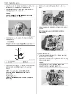
• Clean the mating surfaces of the cylinder head and
head cover before mating.
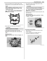
• Install the dowel pins (1) and cylinder head cover plug
to the cylinder head.
NOTE
The groove “A” of the cylinder head cover
plug should face cylinder head side.
1. Camshaft sprocket
4. Locating pin
3. Camshaft
5. Lock washer
“C”
4
I931H1140099-02
1
4
3
5
I931H1140101-02
(a)
(a)
I931H1140100-01
I931H1140102-01
1
“A”
I931H1140103-01
Summary of Contents for 2009 LT-A500XP
Page 2: ......
Page 4: ......
Page 14: ...00 9 Precautions ...
Page 224: ...1E 3 Engine Lubrication System EXHAUST SIDE INTAKE SIDE I931H1150003 02 ...
Page 304: ...1K 4 Exhaust System ...
Page 346: ...2D 5 Wheels and Tires ...
Page 438: ...3D 26 Propeller Shafts ...
Page 482: ...4D 6 Parking Brake ...
Page 512: ...5A 28 Automatic Transmission ...
Page 624: ...Prepared by December 2008 Part No 99500 44080 03E Printed in U S A 624 ...


