6C-52 Power Assisted Steering System:
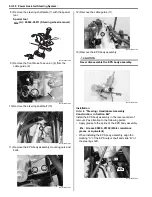
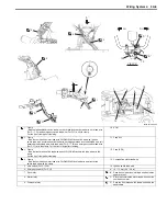
• Install the handlebar holder (7) and tighten the nuts to
the specified torque.
Tightening torque
Handlebar holder nut (e): 60 N·m (6.0 kgf-m, 43.5
lbf-ft)
• Install the center cover (8).
• Install the holder cover (12).
• Install the front fender. Refer to
“Front Side Exterior
Parts Removal and Installation: in Section 9D”
.
• Install the handlebars. Refer to
“Handlebars
Removal and Installation: in Section 6B”
.
• Install the combination meter. Refer to
“Combination
Meter Removal and Installation: in Section 9C”
.
EPS Motor Inspection
B931H26306005
1) Disconnect the EPS motor coupler.
2) First, check for insulation with the tester between
terminals “A” and “B”.
If continuity does not exist, replace the EPS body
assembly with a new one.
Special tool
(A): 09900–25008 (Multi circuit tester set)
Tester knob indication
Continuity (
)
3) Next, check for insulation with the tester between
terminal “A” and body ground “C” and terminal “B”
and body ground “C”.
If continuity is found, replace the EPS body
assembly with a new one.
Special tool
(A): 09900–25008 (Multi circuit tester set)
Tester knob indication
Continuity (
)
8. Center cover
9. Wiring harness (Left handlebar switch/Parking rear brake switch/
Parking rear brake light switch), (Emergency switch (For P-17) and
horn switch (For P-17, 24))
10. Parking/Rear brake cable
11. Steering shaft
“A”: Hooked point
(e)
7
I931H1630081-02
8
9
“A”
11
10
I931H1630091-02
12
I931H1630083-02
“A”
“B”
(A)
I931H1630107-02
“A”
“C”
“B”
(A)
I931H1630108-02
Summary of Contents for 2009 LT-A500XP
Page 2: ......
Page 4: ......
Page 14: ...00 9 Precautions ...
Page 224: ...1E 3 Engine Lubrication System EXHAUST SIDE INTAKE SIDE I931H1150003 02 ...
Page 304: ...1K 4 Exhaust System ...
Page 346: ...2D 5 Wheels and Tires ...
Page 438: ...3D 26 Propeller Shafts ...
Page 482: ...4D 6 Parking Brake ...
Page 512: ...5A 28 Automatic Transmission ...
Page 624: ...Prepared by December 2008 Part No 99500 44080 03E Printed in U S A 624 ...


