


Fuel System: 1G-10
Fuel Pump Disassembly and Assembly
B931H21706012
Refer to “Fuel Pump Assembly Removal and Installation
(Page 1G-9)”.
Disassembly
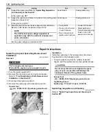
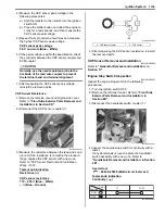
Remove the fuel cup holder (1) with a (–) screw driver.
Assembly
Assemble the fuel tank pump in the reverse order of the
disassembly.
Fuel Mesh Filter Inspection and Cleaning
B931H21706013
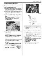
Inspect the fuel mesh filter in the following procedures:
1) Remove the fuel cup holder. Refer to “Fuel Pump
Disassembly and Assembly (Page 1G-10)”.
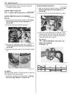
2) If the fuel mesh filter is clogged with foreign particles,
it hinders smooth gasoline flow resulting in loss of
engine power.
NOTE
When the fuel mesh filter is dirtied
excessively, replace the fuel mesh filter with
a new one.
3) After finishing the fuel mesh filter inspection, reinstall
the fuel cup holder and fuel pump assembly. Refer to
“Fuel Pump Assembly Removal and Installation
(Page 1G-9)”.
Fuel Injector Inspection and Cleaning
B931H21706014
Inspect the fuel injector in the following procedures:
1) Remove the fuel injector. Refer to “Fuel Injector /
Fuel Delivery Pipe Removal and Installation
(Page 1G-10)”.
2) Check the fuel injector filter for evidence of dirt and
contamination. If present, clean and check for
presence of dirt in the fuel lines and fuel tank.
3) Install the fuel injector. Refer to “Fuel Injector / Fuel
Delivery Pipe Removal and Installation (Page 1G-
10)”.
Fuel Injector / Fuel Delivery Pipe Removal and
Installation
B931H21706015
Removal
WARNING
!
• Spilled gasoline should be wiped off
immediately.
• Keep away from fire or spark.
• Work in a well-ventilated area.
1) Remove the front fender. Refer to
“Front Side
Exterior Parts Removal and Installation: in
Section 9D”
.
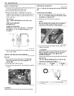
2) Remove the air cleaner box. Refer to
“Air Cleaner
Box Removal and Installation: in Section 1D”
.
1
I831G1170020-01
I931H1170016-01
I931H1170017-01
Summary of Contents for 2009 LT-A500XP
Page 2: ......
Page 4: ......
Page 14: ...00 9 Precautions ...
Page 224: ...1E 3 Engine Lubrication System EXHAUST SIDE INTAKE SIDE I931H1150003 02 ...
Page 304: ...1K 4 Exhaust System ...
Page 346: ...2D 5 Wheels and Tires ...
Page 438: ...3D 26 Propeller Shafts ...
Page 482: ...4D 6 Parking Brake ...
Page 512: ...5A 28 Automatic Transmission ...
Page 624: ...Prepared by December 2008 Part No 99500 44080 03E Printed in U S A 624 ...


