


Drive Chain / Drive Train / Drive Shaft: 3A-6
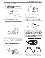
Rear Drive Shaft Components
B931H23106005
Rear Drive Shaft Assembly Removal and
Installation
B931H23106006
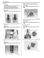
Removal
1) Drain the rear final gear oil. Refer to
“Final Gear Oil
Inspection: in Section 0B”
.
2) Remove the rear wheel. Refer to
“Front / Rear
Wheel Removal and Installation: in Section 2D”
.
3) Remove the rear wheel hub and rear suspension
arm. Refer to
“Rear Wheel Hub / Suspension
Knuckle Removal and Installation: in Section
2C”
.
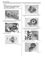
4) Hold the in board joint (1) of the rear drive shaft and
tug the drive shaft horizontally.
NOTE
If it is difficult to remove the rear drive shaft
from the rear differential gear case, using the
suitable tool.
FWD
FWD
1
4
5
6
8
9
2
7
3
10
I931H1310013-04
1. Circlip
6. Inner boot band (Small)
: Apply grease.
2. Snap ring
7. Drive shaft
: Apply water resistance grease.
3. Stopper ring
8. Outer boot band (Small)
: Do not reuse.
4. Inner boot band (Large)
9. Outer boot
5. Inner boot
10. Outer boot band (Large)
1
I931H1310014-02
Summary of Contents for 2009 LT-A500XP
Page 2: ......
Page 4: ......
Page 14: ...00 9 Precautions ...
Page 224: ...1E 3 Engine Lubrication System EXHAUST SIDE INTAKE SIDE I931H1150003 02 ...
Page 304: ...1K 4 Exhaust System ...
Page 346: ...2D 5 Wheels and Tires ...
Page 438: ...3D 26 Propeller Shafts ...
Page 482: ...4D 6 Parking Brake ...
Page 512: ...5A 28 Automatic Transmission ...
Page 624: ...Prepared by December 2008 Part No 99500 44080 03E Printed in U S A 624 ...


