


Precautions: 00-6
4) Using continuity inspect or voltage check procedure
as described below, inspect the wire harness
terminals for open circuit and poor connection.
Locate abnormality, if any.
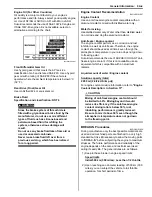
Continuity check
1) Measure resistance across coupler “B” (between “A”
and “C” in figure).
If no continuity is indicated (infinity or over limit), the
circuit is open between terminals “A” and “C”.
2) Disconnect the coupler “B” and measure resistance
between couplers “A” and “B-1”.
If no continuity is indicated, the circuit is open
between couplers “A” and “B-1”. If continuity is
indicated, there is an open circuit between couplers
“B-2” and “C” or an abnormality in coupler “B-2” or
coupler “C”.
Voltage check
If voltage is supplied to the circuit being checked, voltage
check can be used as circuit check.
1) With all connectors/couplers connected and voltage
applied to the circuit being checked, measure
voltage between each terminal and body ground.
2) If measurements were taken as shown in the figure
and results were listed in the following, it means that
the circuit is open between terminals “A” and “B”.
Voltage between
“A” and body ground: Approx. 5 V
“B” and body ground: Approx. 5 V
“C” and body ground: 0 V
3) Also, if measured values are as listed following, a
resistance (abnormality) exists which causes the
voltage drop in the circuit between terminals “A” and
“B”.
Voltage between
“A” and body ground: Approx. 5 V
“B” and body ground: Approx. 5 V – 2 V voltage
drop
“C” and body ground: 3 V – 2 V voltage drop
“D”: Looseness of crimping
“E”: Open
“F”: Thin wire (A few strands left)
“D”
“E”
“F”
I649G1000028-02
ECM
“A”
“B”
“C”
I705H1000006-02
ECM
“A”
“B”
“C”
“B-2”
“B-1”
I705H1000010-02
5V
5V
5V
0V
ECM
“A”
“B”
“C”
“A”
“B”
“C”
I705H1000007-01
Summary of Contents for 2009 LT-A500XP
Page 2: ......
Page 4: ......
Page 14: ...00 9 Precautions ...
Page 224: ...1E 3 Engine Lubrication System EXHAUST SIDE INTAKE SIDE I931H1150003 02 ...
Page 304: ...1K 4 Exhaust System ...
Page 346: ...2D 5 Wheels and Tires ...
Page 438: ...3D 26 Propeller Shafts ...
Page 482: ...4D 6 Parking Brake ...
Page 512: ...5A 28 Automatic Transmission ...
Page 624: ...Prepared by December 2008 Part No 99500 44080 03E Printed in U S A 624 ...


