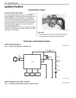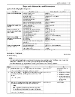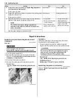
1H-7 Ignition System:
5) After finishing the engine stop switch inspection,
reinstall the removed parts.
Ignition Switch Inspection
B931H21806008
Refer to
“Ignition Switch Inspection: in Section 9C”
.
Ignition Switch Removal and Installation
B931H21806009
Removal
1) Remove the left inner fender. Refer to
“Front Side
Exterior Parts Removal and Installation: in
Section 9D”
.
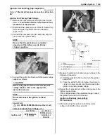
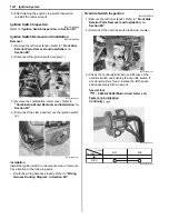
2) Disconnect the ignition switch coupler (1).
3) Remove the combination meter cover. Refer to
“Combination Meter Removal and Installation: in
Section 9C”
.
4) Disconnect the clamp and remove the ignition switch
(2).
Installation
Install the ignition switch in the reverse order of removal.
Pay attention to the following point:
• Route the wiring harness properly. Refer to
“Wiring
Harness Routing Diagram: in Section 9A”
.
Override Switch Inspection
B931H21806010
1) Remove the left inner fender. Refer to
“Front Side
Exterior Parts Removal and Installation: in
Section 9D”
.
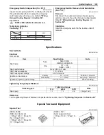
2) Disconnect the override switch read wire coupler.
3) Check the continuity B/W wire and Br wire of the
override switch and pushing the override switch. If
any abnormality is found, replace the left handle
switch assembly with a new one.
Special tool
: 09900–25008 (Multi-circuit tester set)
Tester knob indication
Continuity (
)
1
I931H1180009-01
2
I931H1180010-01
I931H1180011-01
I931H1180001-01
Bl/B
B/W
Color
Position
PUSH
I831G1180014-02
Summary of Contents for 2009 LT-A500XP
Page 2: ......
Page 4: ......
Page 14: ...00 9 Precautions ...
Page 224: ...1E 3 Engine Lubrication System EXHAUST SIDE INTAKE SIDE I931H1150003 02 ...
Page 304: ...1K 4 Exhaust System ...
Page 346: ...2D 5 Wheels and Tires ...
Page 438: ...3D 26 Propeller Shafts ...
Page 482: ...4D 6 Parking Brake ...
Page 512: ...5A 28 Automatic Transmission ...
Page 624: ...Prepared by December 2008 Part No 99500 44080 03E Printed in U S A 624 ...


