8-18
Parameter Value Assignment
RD 500 RD51
DOK-RD500*RD51*******-IB04-EN-P
x-times overcurrent P0566
x-times
overcurrent
P0566
Release time
2 h
1
2
3
4
5
6
7
8
9
10
10
20
30
40
50
60
70
80
90
100
sec
1,15
8
3
4
5
6
7
10
1,05
20min
7,3 s
22,5 s 15,4 s 12 s 9,8 s 8,4 s
5,8 s
DG510003EN00.FH9
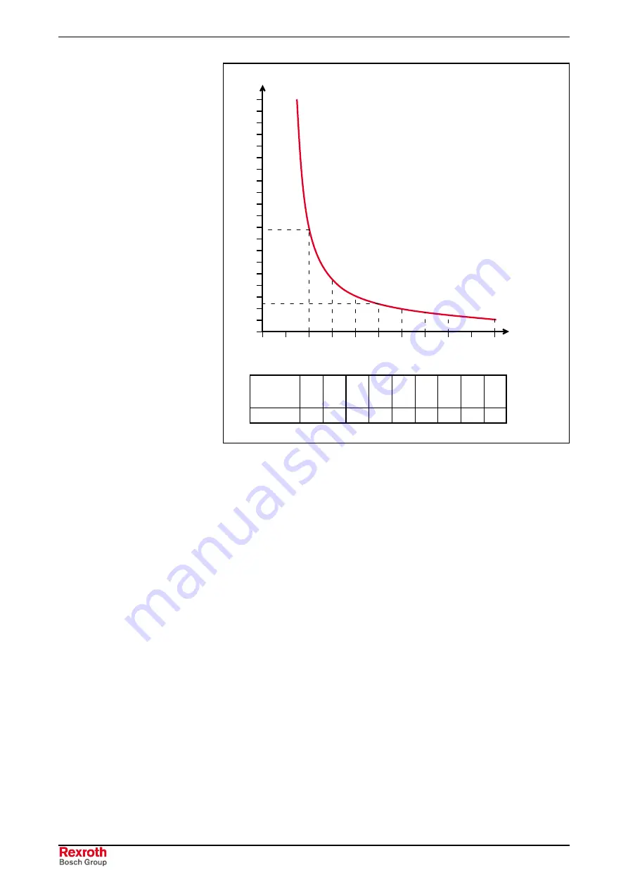
Fig. 8-5: Emulation of the thermal overload release
The overload protection is switched-in and switched-out using P0565 and
the response type, either alarm or fault, is selected.
The response threshold of the overload protection (P0566) can be set
between 0.5 A and the peak current P0025. The overload function was
implemented corresponding to the Siemens 3UB1 overload relay, Class
10 setting.
The delay time until the drive is ready to be powered-up after „overload
protection“ fault depents on the response threshold:
•
For P0566 < 20 A, the drive converter can be powered-up again after
1 minute.
•
For P0566 > 20 A, the drive converter can be powered-up again after
10 minutes.
As long as the delay time is running, after the fault has been successfully
acknowledged, the „motor overload“ alarm is displayed. The drive cannot
be powered-up again during this time.
Overload protection
Summary of Contents for RD 500 Series
Page 32: ...2 12 Description of RD51 RD 500 RD51 DOK RD500 RD51 IB04 EN P...
Page 174: ...5 34 Inverter Technical Data RD 500 RD51 DOK RD500 RD51 IB04 EN P...
Page 248: ...9 4 Commissioning RD 500 RD51 DOK RD500 RD51 IB04 EN P...
Page 274: ...14 6 Index RD 500 RD51 DOK RD500 RD51 IB04 EN P...
Page 275: ......


