RADWIN
5000
HPMP
User
Manual
Release
3.5.70
4
‐
31
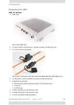
Unpacking
the
VMU
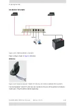
Installation
Schematic
Figure
4
‐
41:
VMU
installation
schematic
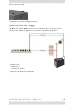
Power
wiring
is
shown
in
below.
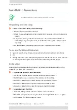
Antenna
Figure
4
‐
42:
Typical
composite
“Shark
‐
Fin”
antenna,
for
radio
broadband,
WiFi
and
GPS
Two
multipurpose
“shark
‐
fin”
antennas
are
mounted
on
the
rear
of
the
vehicle
roof
about
a
meter
apart.
They
should
be
ordered
separately.
Summary of Contents for 5000 HPMP
Page 1: ...USER MANUAL RADWIN 5000 POINT TO MULTIPOINT BROADBAND WIRELESS Release 3 5 70...
Page 21: ...Part 1 Basic Installation Release 3 5 70...
Page 69: ...Part 2 Sector Installation Release 3 5 70...
Page 155: ...Part 3 Sector Management Release 3 5 70...
Page 197: ...RADWIN 5000 HPMP User Manual Release 3 5 70 8 42 Nomadic...
Page 252: ...RADWIN 5000 HPMP User Manual Release 3 5 70 11 8 Registering HMUs 3 Open the Air Interface tab...
Page 290: ...Part 4 Site Synchronization Release 3 5 70...
Page 319: ...RADWIN 5000 HPMP User Manual Release 3 5 70 16 7 Configuring the GSU...
Page 320: ...Part 5 Advanced Installation Topics Release 3 5 70...
Page 354: ...Part 6 Field Installation Topics Release 3 5 70...
Page 396: ...Part 7 Product Reference Release 3 5 70...
Page 517: ......

