background image

RADWIN


5000


HPMP


User


Manual

Release


3.5.70

C

74

MIB


Traps

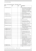
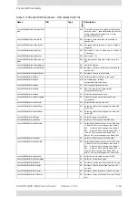
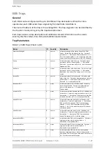
hbsUnregisteredUnsynchronizedHsu

31

normal

Indicates


an


unregistered


HSU


lost


synchronization.


cableQuality

32

normal

1Gbps


rate


is


not


supported


due


to


bad


line


quality.

httpAuthentication

33

normal

HTTP


Authentication


Failure.

telnetAuthentication

34

normal

Telnet


Authentication


Failure.

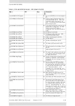
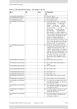
tdmServiceAlarm

100

major

Indicates


that


TDM


Service


is


in


alarm


state.


Contains


a


single


parameter


which


is


its


description:


1

 ‐ 

Description:


TDM


Service

 ‐ 

Alarm.


ethServiceClosed

101

major

Indicates


that


Ethernet


Service


is


closed.


Contains


a


single


parameter


which


is


its


description:


1

 ‐ 

Description:


Ethernet


Service


is


closed.


ethServiceNotPermitted

102

major

Indicates


that


Ethernet


Service


is


not


permitted.


Contains


a


single


parameter


which


is


its


description:


1

 ‐ 

Description:


A


valid


IDU


could


not


be


detected


at


%s.


Please


check


your


configuration.


%s

 ‐ 

Is


the


Local


Site


name


or


Remote


Site


name


or


both


sides


of


the


Link.


encryptionAlarm

103

major

Indicates


an


encryption


key


mismatch.


Contains


a


single


parameter


which


is


its


description:


1

 ‐ 

Description:


Encryption


Status

 ‐ 

Failed.


No


Services


are


available.


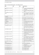
changeLinkPasswordAlarm

104

major

Indicates


that


a


failure


has


occurred


while


attempting


to


change


the


Link


Password.


Contains


a


single


parameter


which


is


its


description:


1

 ‐ 

Description:


Failed


to


change


the


Link


Password


at/on:


%s.


%s

 ‐ 

Is


the


Local


Site


name


or


Remote


Site


name


or


both


sides


of


the


Link.


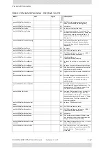
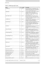
externalAlarmInPort1Alarm

105

major

The


trap


is


sent


every


time


an


alarm


occurs


in


the


External


Alarm


Input


of


port


#1.


Contains


a


single


parameter


which


is


its


description:


1

 ‐ 

Description:


External


Alarm


1

 ‐ 

<User


Text>

 ‐ 

Alarm.


externalAlarmInPort2Alarm

106

major

The


trap


is


sent


every


time


an


alarm


occurs


in


the


External


Alarm


Input


of


port


#2.


Contains


a


single


parameter


which


is


its


description:


1

 ‐ 

Description:


External


Alarm


2

 ‐ 

<User


Text>

 ‐ 

Alarm.


bitFailedAlarm

107

major

The


trap


is


sent


if


there


is


no


way


to


recover


from


the


situation.Contains


two


parameters:


1

 ‐ 

Description:


ODU


power


up


built


in


test


failed.


Error


code


is:


%n


2

 ‐ 

%n


number


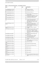
wrongConfigurationLoadedAlarm

108

major

The


trap


is


sent


if


there


is


a


way


to


recover


from


the


situation.Contains


two


parameters:


1

 ‐ 

Description:


Wrong


configuration


loaded.


Error


code


is:


%n


2

 ‐ 

%n


number


lanPort1DisconnectedAlarm

109

major

Indicates


the


LAN


port


1


status


changed


to


disconnected.Contains


a


single


parameter


which


is


its


description:


1

 ‐ 

Description:


LAN


port


1


status


changed


to


disconnected.


lanPort2DisconnectedAlarm

110

major

Indicates


the


LAN


port


2


status


changed


to


disconnected.Contains


a


single


parameter


which


is


its


description:


1

 ‐ 

Description:


LAN


port


2


status


changed


to


disconnected.


mngPortDisconnectedAlarm

111

major

Indicates


the


management


port


status


changed


to


disconnected.Contains


a


single


parameter


which


is


its


description:


1

 ‐ 

Description:


Management


port


status


changed


to


disconnected.


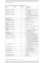
externalAlarmInPort3Alarm

112

major

The


trap


is


sent


every


time


an


alarm


occurs


in


the


External


Alarm


Input


of


port


#3.


Contains


a


single


parameter


which


is


its


description:


1

 ‐ 

Description:


External


Alarm


3

 ‐ 

<User


Text>

 ‐ 

Alarm.


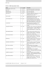
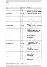
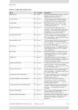
Table


C

4:


MIB


Traps


(Sheet


3


of


8)

Name

ID

Severity

Description

Summary of Contents for 5000 HPMP

Page 1: ...USER MANUAL RADWIN 5000 POINT TO MULTIPOINT BROADBAND WIRELESS Release 3 5 70...

Page 2: ...ted from and shall not directly or indirectly develop market distribute license or sell any product that supports substantially similar functionality based or derived in any way from RADWIN products Y...

Page 3: ...ase 3 5 70 ii Windows 2000 XP Pro Vista Windows 7 and Internet Explorer are trademarks of Microsoft Inc Mozilla and Firefox are trademarks of the Mozilla Foundation Other product names are trademarks...

Page 4: ...mail salesmx radwin com RADWIN Peru Av Antares 213 Lima 33 Peru Tel 511 6285105 Fax 511 990304095 Email salespe radwin com RADWIN India E 13 B 1 Extn Mohan Co operative Industrial Estate New Delhi 110...

Page 5: ...to correct the interference by one or more of the following measures Reorient or relocate the receiving antenna Increase the separation between the equipment and receiver Connect the equipment into a...

Page 6: ...ust be considered during installation Caution Outdoor units and antennas should be installed ONLY by experienced installation professionals who are familiar with local building and safety codes and wh...

Page 7: ...tning and power conductors in accordance with NEC Sections 725 54 c and 800 30 In all other cases an appropriate Listed Primary Protector must be provided Refer to Articles 800 and 810 of the NEC for...

Page 8: ...te Synchronization Chapter 13 Hub Site Synchronization Chapter 14 Serial Hub Site Synchronization Chapter 15 Hub Site Synchronization over Ethernet Chapter 16 Using the RADWIN GSU Part 5 Advanced Inst...

Page 9: ...iew 4 1 What s in the box 4 2 Tools required for installation 4 12 Safety Practices and Provisions 4 13 Regulatory Considerations for HSUs 4 15 Hardware Installation Workflow for a RADWIN 5000 Sector...

Page 10: ...Chapter 7 1 Bringing up a Sector 7 1 HSU Operation 7 2 Part 3 Sector Management Chapter 8 Managing the Sector Scope of this Chapter 8 1 Configuring a HBS 8 1 HSU Connection Table 8 30 Configuring an H...

Page 11: ...1 RADWIN HSS 13 1 HSS Concepts Radio Frame Pattern RFP 13 4 Which Type of HSS to Use 13 5 Chapter 14 Serial Hub Site Synchronization RADWIN Serial HSS 14 1 Hardware Installation 14 1 ODU HSS Unit Con...

Page 12: ...rt 6 Field Installation Topics Chapter 23 Link Budget Calculator Overview 23 1 Calculations 23 2 About the Fresnel Zone 23 3 Running the Link Budget Calculator 23 5 Chapter 24 Spectrum View What is Sp...

Page 13: ...na Characteristics A 18 Appendix B Wiring Specifications ODU PoE Cable HBS and HSU B 1 HBS HSS Unit Connection Pinout B 2 User Port Connectors B 3 DC Power Terminals B 4 VMU Connectors B 4 Appendix C...

Page 14: ...URE 4 21 USING AN ETHERNET REPEATER WITH LIGHTNING PROTECTORS 4 12 FIGURE 4 22 MOUNTED ODU MOUNTED TO A WALL 4 16 FIGURE 4 23 MOUNTED ODU LARGE ANGLE TO WALL 4 17 FIGURE 4 24 MOUNTED ODU HORIZONTAL PO...

Page 15: ...ON TOOL BAR 5 30 FIGURE 5 29 HSU STATUS CARDS INDICATING PROBLEMS 5 32 FIGURE 5 30 HSU STATUS CARDS LEFT FIXED HSU RIGHT NOMADIC HSU 5 32 FIGURE 5 31 HSU DISPLAY CONTEXT MENU RIGHT CLICK 5 33 FIGURE 5...

Page 16: ...2 FIGURE 9 2 REGISTERED HSU EXTENDED VIEW 9 2 FIGURE 9 3 DIRECT CONNECTION TO A STAND ALONE HSU OUT OF THE BOX 9 3 FIGURE 9 4 HSU CONFIG AIR INTERFACE FOR REGISTERED FIXED HSU 9 4 FIGURE 9 5 HSU CONF...

Page 17: ...ING INVALID DATA 12 12 FIGURE 12 10 HSU PERFORMANCE MONITORING VALID AND INVALID DATA 1 OF 3 12 13 FIGURE 12 11 HSU PERFORMANCE MONITORING VALID AND INVALID DATA 2 OF 3 12 13 FIGURE 12 12 HSU PERFORMA...

Page 18: ...9 WORLD MAP SHOWING C FACTOR CONTOURS 23 10 FIGURE 23 10 LBC RESULTS SECTION 23 11 FIGURE 24 1 SPECTRUM VIEW DATA PANEL FOR THE HBS READY FOR DATA 24 5 FIGURE 24 2 SPECTRUM VIEW ANALYSIS COLOR CODES 2...

Page 19: ...PRECONFIGURED SETUP ONE NOMADIC HSU 6 8 TABLE 8 1 SNMPV3 PREDEFINED USERS 8 12 TABLE 8 2 AES INDICATORS FOR AN HBS 8 55 TABLE 8 3 AES INDICATORS FOR AN HSU 8 55 TABLE 8 4 HBS TELNET DISPLAY COMMANDS 8...

Page 20: ...POE RJ 45 CONNECTOR PINOUT B 1 TABLE B 2 LAN GBE POE RJ 45 CONNECTOR PINOUT B 1 TABLE B 3 HBS HSS UNIT CONNECTION PINOUT B 2 TABLE B 4 FAST ETHERNET CONNECTOR PINOUT B 3 TABLE B 5 TERMINAL BLOCK 2 PIN...

Page 21: ...Part 1 Basic Installation Release 3 5 70...

Page 22: ...ite preparation and hardware Installation 2 Sector Installation Understanding the RADWIN Manager windows Using the RADWIN Manager to bring up a sector 3 Sector Configuration and Management Fine tuning...

Page 23: ...ccasionally we use a Note as a Tip Warning A Warning is a notification of risk of danger to persons operating near the equipment Caution A Caution is a notification of risk of damage to equipment or o...

Page 24: ...d and channel bandwidth Adjacent Sectors in a PtMP network will typically use different frequencies and non overlapping bands to mitigate HBS self interference A HSU may be defined as fixed nomadic or...

Page 25: ...bles service capacity of up to 100Mbps for enterprise customers There are three types of RADWIN 5000 subscriber units Fixed permanently installed at fixed locations Nomadic installed in a vehicle that...

Page 26: ...or 3 3 3 8 or 4 9 6 0 or 5 9 6 4 GHz in the same unit Simple to deploy Web Interface for sector management both HBS and HSU SFP support when connecting to a IDU H in place of a PoE device Mobility Cap...

Page 27: ...and down link per HSU at the HBS Separate uplink and downlink configurable Maximum Information Rate MIR per HSU Upgradable subscriber unit capacity using a software key Fixed nomadic mobility types Co...

Page 28: ...of directional and sector antennas is available ODU and antenna mounting kits Lightning protector for use with all RADWIN outdoor products Ethernet repeater enables you to extend non GbE PoE ODU cabl...

Page 29: ...RADWIN links1 The intuitive easy to use RNMS provides a full range of network surveillance monitoring configuration and fault management capabilities It offers users complete visibility and control ov...

Page 30: ...or the Radio Plan ner 2 Physical survey The locations of the indoor and outdoor equipment are determined on site 3 Radio Frequency RF survey It is recommended that the installation area be scanned wit...

Page 31: ...on sites As much detail as possible should be obtained about the designated ODU installation sites and the area between them To perform a preliminary survey 1 Mark the designated installation sites on...

Page 32: ...azimuth hori zontal position that each fixed HSU should face towards the HBS 2 Using binoculars locate any obstructions such as tall trees high buildings hills or mountains Look for other RF towers b...

Page 33: ...0 non condensing Stage 3 RF Survey The RF survey examines the wireless environment of the installation site to determine whether there are available channels within the radio operating frequency band...

Page 34: ...nd any other collocated radio on the site Use the largest possible frequency gap between these units Choose the best frequency channel as clear as possible from interference You may be able to change...

Page 35: ...unting an ODU Connecting an ODU Grounding and lightning protection for an ODU Warning Outdoor units and antennas should be installed ONLY by qualified field technicians who are familiar with local bui...

Page 36: ...forma Invoice is present 3 If any item is missing contact Customer Service You will be advised if the package should be returned for replacement or if the missing item will be supplied separately 4 Do...

Page 37: ...rence Cable glands to be used with the HBS PoE cable Quick Start Guide leaflet Subscriber Units The RADWIN 5000 HPMP HSU package include the following items One HSU Large form factor as shown in Figur...

Page 38: ...r Unit the Vehicular Mobile Unit The Vehicular Mobile Unit is a ruggedized Mobile Radio Unit VMU specially designed for deployment in vehicles or in a fully outdoor environment connecting directly to...

Page 39: ...rmance Broadband network connectivity for devices in and around the vehicle High Capacity Mobile Unit up to 100Mbps Wide coverage up to 10 km 6 miles High speed up to 250Km h 150 miles h 802 11b g n A...

Page 40: ...HBS and the HSUs It does not support Gigabit performance on the HBS Two models are available using power input of 20 to 60 VDC or 10 to 30 VDC The unit can be installed in a vehicle using respectively...

Page 41: ...nted side by side Two DC power plugs for power cables see Figure 4 10 below Figure 4 10 DC three pin power plug The power connectors are 3 pin in line female with polarities left to right minus ground...

Page 42: ...configuration External Antennas HBS Sector Antennas The HBS requires a dual pole sector antenna Figure 4 13 External Antennas for HBS 60 90 or 120 flat panel HSU Directional Antennas HSUs may use any...

Page 43: ...rying in operating frequencies form factor size and gain See the RADWIN products catalog for a more detailed offering of external antennas External A typical antenna kit contains An antenna Two RF cab...

Page 44: ...nnect to this box using an HSS cable A variety of cables of different lengths are available for purchase The HSS unit is supplied with ten protective covers any port not in use must be closed with a p...

Page 45: ...ion using both Ethernet and an HSS unit Lightning Protector Unit LPU The use of lightning protection is dependent on regulatory and end user requirements The RADWIN 5000 ODU is designed with surge lim...

Page 46: ...device in Figure 4 20 Its use is very simple as shown in the following schematic Figure 4 21 Using an Ethernet repeater with lightning protectors Tools required for installation The following is a li...

Page 47: ...is on The ODU must not be deployed in a location where it is possible for people to stand or walk inadvertently in front of the antenna Grounding All RADWIN products should be grounded during operatio...

Page 48: ...dditional surge arrestor devices to protect the equipment from nearby lightning strikes General It is recommended that installation of outdoor units be contracted to a professional installer Before wo...

Page 49: ...indoors Ensuring availability of power typically standard local AC power Ensuring that there is a LAN cable in place from the user s switch to the PoE location Warning When installing an AC powered H...

Page 50: ...DU to be mounted at large angles relative to the wall or pole or to a horizontal pole as shown Note When mounting an ODU on a pole or wall ensure that the unit is ori ented so that the cable connector...

Page 51: ...tion Figure 4 23 Mounted ODU large angle to wall Figure 4 24 Mounted ODU horizontal pole Mounting an HBS External Antenna The HBS requires a sector antenna Typically a flat panel antenna such as that...

Page 52: ...ear The right hand view shows the recess for the mounting kit holding nut Figure 4 26 Flat Panel antenna rear with mounting kit adapter Grounding an HBS external antenna External antennas should be in...

Page 53: ...evice to a Network Connect the PoE to network equipment such as a switch from the LAN In port Connecting network equipment to the LAN Out port may damage it Powering up the HBS from a Poe Device Conne...

Page 54: ...type of RADWIN IDU used with such products PoEs IDU H etc For any type of IDU ODU connection lightning protection units LPUs are installed in pairs as shown in the next figure Table 4 1 LPU Kit conten...

Page 55: ...he pole using the grounding lug 3 Connect the 0 5 meter CAT 5e cable to the IDU port of the ODU 4 Connect the other end of the cable to the top of the LPU 5 Tighten the top cable LPU gland cap 6 Conne...

Page 56: ...ccess point to the IDU 9 Insulate both LPU connections See the next section Additional Considerations for Waterproofing below Additional Considerations for Waterproofing Lightning Protectors and Ether...

Page 57: ...the CAT 5e cable Start at Start Point at the bottom of the cable gland as shown in Figure 4 30 Finish at End Point of the CAT 5e cable 2 5cm after the end of the shrink tubing Stretch the tape and app...

Page 58: ...g the mounting ring as shown in Figure 4 32 Ground the unit using the GND screw For lightning protection repeat the same procedure to install the second unit connected to the IDU Figure 4 32 Mounted a...

Page 59: ...re 4 12 Connecting the HBS to an IDU H Connect the HBS IDU port to any of the six PoE ports of the IDU H Connecting the IDU H device to a network The IDU H has two LAN ports either of which may be use...

Page 60: ...14 to Figure 4 16 use the standard mounting kit Some third party antennas use pole clamps similar to those shown below Table 4 2 IDU H LED Indicators Port Green Yellow WAN 2xRJ45 LEDs Link Activity D...

Page 61: ...e 223158 2 http www commscope com The same considerations as for the HBS antennas apply here Grounding the HSU All HSUs have a grounding lug as shown in Figure 4 37 Connect it to ground using 10 AWG w...

Page 62: ...tion connector of the antenna to the ANT 2 connector of the ODU 3 Ensure that power is connected to the site PoEs across the sector An unaligned HSU starts beeping 20 seconds after power up and contin...

Page 63: ...rts for CAT 5e Cables The same considerations as for an HBS hold for the HSUs HSU AC Power ports They should also we waterproofed in the same manner as the other ports Installing a Vehicular Mobile Un...

Page 64: ...Fuses for power and ignition Figure 4 40 In line water proof fuse holder for 14AWG 20A and 12AWG 30A wiring 1 x LAN cable 7m with female M12 connector and RJ 45 connector Installation kit including M...

Page 65: ...4 41 VMU installation schematic Power wiring is shown in Figure 4 44 below Antenna Figure 4 42 Typical composite Shark Fin antenna for radio broadband WiFi and GPS Two multipurpose shark fin antennas...

Page 66: ...Figure 4 43 Mounted twin Shark Fin antennas Motor Vehicle Power Supply The VMU works with 10 36V DC power It may be installed without special provisions in ordinary motor vehicles using a 12V power o...

Page 67: ...g tape such as Scotch 23 Tape wide from 3M to ensure protection against water and dust for cable entry into the vehicle Installation Mount the VMU in a safe protected location The ambient temperature...

Page 68: ...tly to the car chassis use sheet metal screws and star washers 5 If the unit is mounted on a non metallic surface such as plastic or wood use suitable screws or bands 6 Fasten the screws to secure the...

Page 69: ...Part 2 Sector Installation Release 3 5 70...

Page 70: ...cquired here will enable you to understand the direction and purpose of the detailed procedures described in later chapters required to build a RADWIN 5000 sector from the ground up Installing the RAD...

Page 71: ...e Software Any PC running the RADWIN Manager application can be used to configure a RADWIN 5000 HPMP sector To install the RADWIN Manager application 1 Insert the CD into the CD DVD drive of your comp...

Page 72: ...Prefix Length 32 Default Gateway 2005 104 20 21 Sector ID EBGX20560334 Inherited by all communicating fixed HSUs Network ID EBX Inherited by all communicating nomadic Protocol SNMPv1 Can be set to SN...

Page 73: ...wnlink 8 May vary with context Uplink 2 Unit Serial Number P07030E000A0003E Geographic location Latitude 37 89651 Longitude 145 15716 Antenna height m 10 From RF plan not used HFU 01 02 IPv4 Address 1...

Page 74: ...o SNMPv3 or both v1 Contact Handel Optional Name Handel HFU 01 04 Location of Contact optional Time Slots Downlink 8 May vary with context Uplink 2 Unit Serial Number P07030E000A0003B Supports AES 256...

Page 75: ...in the same subnet Net Mask 255 255 0 0 Default Gateway 10 104 10 21 IPv6 Address 2005 104 50 3 Subnet Prefix Length 32 Default Gateway 2005 104 20 21 Protocol SNMPv1 Can be set to SNMPv3 or both v1 C...

Page 76: ...esponse from ping means that the HBS ODU is not responding Check your Ethernet connection and that both the PoE and ODU are switched on and then try again If you do not succeed seek assistance from RA...

Page 77: ...together The log on procedure differs slightly between operation under SNMPv1 and SNMPv3 In what follows below we assume that SNMPv1 is in use In Table 5 6 at end of the section we show the difference...

Page 78: ...y access to the sector An Observer can monitor the sector generate reports but may not change any sector parameters An Operator can install and configure the sector An Installer can in addition to fun...

Page 79: ...essage address associated with a defined user The allocation and association of a trap address with a user is described in Chapter 8 Management If you are connecting through the RNMS server check the...

Page 80: ...he Community options if required Log on Errors and Cautions Unsupported Device Attempting to connect to an unsupported device on an otherwise valid IP address for example a LAN printer will result in...

Page 81: ...igure 5 9 To deal with lost or forgotten Community Strings 1 Send an email request for to RADWIN Customer Service for an alternative key Your email must include the ODU serial number shown on the adhe...

Page 82: ...13 Four Sector Display Views Four Sector Display Views Table View The RADWIN Manager offers three sector display views The default view for a freshly installed sector is Table view and looks like this...

Page 83: ...of balance there may be a problem with the HBS The Level in the nomadic HSU There are four allowed levels A to D allowing a measure of prioritization of nomadic HSUs We will see how this is done on pa...

Page 84: ...low Map View If you have an Internet connection you may use Map view The map view uses distinctive icons to distinguish between different types of HSUs and the HBS Figure 5 13 Map view icons The green...

Page 85: ...hin the sector beam width configurable without regard for geographic considerations If you do not have an Internet connection the display background will be solid gray For this demonstration we use a...

Page 86: ...rther details about the displayed HSUs The Index and Name fields are protected so you always know to which HSUs the data belongs The status indicator ball has the same meaning as it does for the HSU c...

Page 87: ...RADWIN 5000 HPMP User Manual Release 3 5 70 5 18 List View The grayed out items are always displayed The other checked items are shown by default but may be removed...

Page 88: ...s It is particularly important since the SBM mechanism can temporarily assign unused downlink time slots to a very busy HSU It can also temporarily assign unallocated uplink time slots for the same pu...

Page 89: ...r which the Maps view is very helpful Continuing with our Example Sector Using the Map View To set up a new sector or to carry out substantial changes to an existing sector you should have a Radio Pla...

Page 90: ...the coordinates in decimal or degrees minutes seconds using the input template shown below 3 HBS only The Azimuth and Beam Width determine the sector center line direction and angle They are only used...

Page 91: ...ace holders for additional nomadic HSUs You can make manual location adjustments using the GUI To relocate a HBS or HSU using the GUI 1 Select the unit to move by clicking it It is surrounded by a bro...

Page 92: ...n to its new location You must confirm the change Table 5 8 Unit Context Button bar functions Button Tool tip Purpose Left Show Hide details Show Hide the status window Center Unlock Lock Item Unlock...

Page 93: ...r functions Menu Item Purpose Cross Reference Preferences Monitor File location interval and throughput units Monitor Events Color coding for events log and events log file location Events Advanced En...

Page 94: ...en allocated to HSUs Allocation of time slots between HSUs provides a basic form of prioritization between them Normally you would not leave unallocated time slots unless you intended to add more HSUs...

Page 95: ...iates an activation Wizard The Activate button in the title bar is hidden leaving it looking like this The Activation process is covered in detail in Chapter 6 At any time the current status of the HB...

Page 96: ...and alarms see Chapter 12 The events are displayed in the Events Log in the lower right hand panel of the RADWIN Manager main window Figure 5 22 Events Log panel The events log provides a color coded...

Page 97: ...wing choices The following case has colored fields indicating a problem requiring your attention Figure 5 24 HSU card indicating a problem If you mouse over the colored RSS area you will receive a too...

Page 98: ...5 29 HBS Main Window HSUs Panel Map View Here again is the Map view of the HBS Main Window Figure 5 26 HBS Main Window Map view HBS HSU Status Lights HBS HSU Status light appear on the tower graphic...

Page 99: ...n the example Figure 5 28 Navigation Tool bar Table 5 11 HBS HSU Status light color codes Figure 5 27 HBS HSU Status lights Color Description HBS HSU Green Active Registered in sync Red Inactive Regis...

Page 100: ...the view to zoom out become smaller less detailed Moving the mouse over the map with the right button depressed drags the sector cen tered on the HBS in the direction of movement Right clicking anywh...

Page 101: ...but it may be easily corrected using Configure Tx Antenna or by rerunning the Configuration wizard A yellow warning color will be displayed for an RSS difference of more than 8 dBm between the two po...

Page 102: ...e sector with a small display Right click an HSU image to get its context menu Figure 5 31 HSU display context menu right click List View List view functionality is obtained ny selecting a HSU and usi...

Page 103: ...m Menu Icon Purpose Cross Reference Register Register a HSU to a sector Registering a fixed HSU for service Configure Site configuration for the HSU Configuring an HSU from the HBS Main Window Recent...

Page 104: ...ablished sector The log on procedure is the same as for a HBS Suppose we log on to HSU with IP address 10 104 50 1 We initially receive the following caution Figure 5 33 Logging on to a HSU Upon click...

Page 105: ...on to a HSU The direct log on window differs only in the bottom status bar where the Connection Mode will show Network instead of Over the air There are several functional differences between the log...

Page 106: ...functions in the detail menu work in the same way as the corresponding functions for the HBS See Software Backup and Upgrade for the fifth and sixth items Preferences Monitor File location interval a...

Page 107: ...nctionally identical to that of the HBS HSU Link Performance For convenience The HSU Link Performance panel shows the same fields as in Figure 5 30 For convenience we also display the corresponding pa...

Page 108: ...relate entirely to the way the Manager displays certain items for the connected unit They are completely local to the managing computer They are also functionally very similar for both the HBS and HS...

Page 109: ...by Google Earth The latter will show you the points traversed by VMUs during the recording period For a HSU it will record the information just for that HSU You should use distinctive file names for H...

Page 110: ...e again per HBS or HSU To avoid over writing you should use file names reflecting their source ODU The SNMPv3 User and Password are relevant if you are using SNMPv3 In this case trap messages are keye...

Page 111: ...0 HPMP User Manual Release 3 5 70 5 42 Advanced Advanced Figure 5 38 Advanced Preferences HBS Figure 5 39 Advanced Preferences HSU Change Password You may change your log on password here from the def...

Page 112: ...Intervals The monitoring interval determines the lowest interval between request to the ODU for status updates The timeout default 1 sec maximum 5 sec may have to be increased if you are on a slow ne...

Page 113: ...nt where setup procedures are common we will point them out This chapter covers fixed and nomadic HSU configurations Mobile HSUs are covered in Chapter 11 Concepts A HBS out of the box must be configu...

Page 114: ...They are covered in Chapter 11 Working with Nomadic HSUs Each nomadic HSU is allocated to one of four HBS levels labelled A B C and D Some operating parameters for each level such as VLAN MIR QoS time...

Page 115: ...Default settings Unit Parameter Default Value HBS IP Address 10 0 0 120 Net Mask 255 0 0 0 Default Gateway 0 0 0 0 Location Location Contact Person Name Contact Protocol SNMPv1 Factory default band Pr...

Page 116: ...ress 10 0 0 120 Net Mask 255 0 0 0 Default Gateway 0 0 0 0 Location Location Contact Person Name Name Protocol SNMPv1 RADWIN Manager log on passwords Observer admin Operator admin Installer wireless L...

Page 117: ...04 50 200 Subnet Prefix Length 32 Default Gateway 2005 104 20 21 Sector ID EBGX20560334 Inherited by all communicating fixed HSUs Network ID EBX Inherited by all communicating nomadic Protocol SNMPv1...

Page 118: ...ink 8 May vary with context Uplink 2 Unit Serial Number P07030E000A0003E Geographic location Latitude 37 89651 Longitude 145 15716 Antenna height m 10 From RF plan not used HFU 01 02 IPv4 Address 10 1...

Page 119: ...NMPv3 or both v1 Contact Handel Optional Name Handel HFU 01 04 Location of Contact optional Time Slots Downlink 8 May vary with context Uplink 2 Unit Serial Number P07030E000A0003B Supports AES 256 Ge...

Page 120: ...e Value Remark HNU 01 01 IPv4 Address 10 104 50 3 All communicating HSUs and HBS in the same subnet Net Mask 255 255 0 0 Default Gateway 10 104 10 21 IPv6 Address 2005 104 50 3 Subnet Prefix Length 32...

Page 121: ...connection is not local i e anything other than a direct connection between the managing computer and the PoE device then any configuration you carry out may affect other links in the network Do not...

Page 122: ...support IPv4 style broadcast ing 2 If you are confronted with an ODU configured for IPv6 and you do not have it s IP address there is no simple way to log on to the unit This is a limitation of IPv6...

Page 123: ...nd activated Here is the work flow 4 Activate the HBS which includes setting its IP address It will then see the deployed HSUs regardless of their IP address 5 Configure the HSUs 6 Register the HSUs t...

Page 124: ...anged while linked It is locked into the HBS This mechanism prevents an HSU close to a sector boundary from drifting between HBSs for adjacent sectors Notice that the Sector ID is split into two parts...

Page 125: ...the split Sec tor ID is explained on page 9 4 Choose your Sector ID it carefully particularly if you are using collocated HBSs for extra coverage The Sector Name and Location are convenience items but...

Page 126: ...be found on page 8 19 It is best left as is if there is no pressing need to change it 5 From the previous Activation Wizard window click Next Here you may enter the IP details if didn t do it earlier...

Page 127: ...6 15 The Initial RADWIN Manager Main Window The default frequency is the lowest available 5 735 GHz in the operating band here 5 730 5 845 GHz FCC IC 7 Click Other to see other available bands for thi...

Page 128: ...is no longer displayed Had you left Other enabled you could have chosen a frequency by working through those available in 5MHz increments 9 Choose the required Channel Bandwidth 10 To use ACS check t...

Page 129: ...n Window You can perform a customized channel selection or click Select All to check all the channel boxes as shown Automatic channel selection at the HBS makes little sense beyond configuration time...

Page 130: ...tallation you might like to consider the background information about setting antenna parameters in Appendix E Choose your Antenna Type Required Tx Power Antenna Gain and Cable Loss We will set Requir...

Page 131: ...5 70 6 19 The Initial RADWIN Manager Main Window Check that all information showed is correct and click Activate After a few moments the sector HSUs will be displayed in the Manager HSU panel The fiel...

Page 132: ...HBS tries to optimize the frequency to minimize interference effects We next configure and register the HSUs For fixed HSUs you can do this in either order For nomadic HSUs you must define the HSU as...

Page 133: ...s context menu Figure 6 5 HSU Context menu 2 Click Configure The Configuration dialog is displayed If you have not already enter a Name Contact and Location Location is a site name typically a buildin...

Page 134: ...70 6 22 Configuring a fixed HSU From the HBS 3 Set the Coordinates latitude and longitude for the HSU as shown in the Sector Plan 4 Set the HSU Tx Power possibly as required by regulations Click Tx A...

Page 135: ...e Antenna Type Required Tx Power Antenna Gain and Cable Loss as required For our example we use external antennas we set Tx Power to 5 dBm and the Antenna Gain to 15 dBi If you click apply you receive...

Page 136: ...HSU From the HBS 5 In any event clicking Yes results in a further message appearing 6 Click OK The HSU display area refreshes with the newly configured HSU in its new location in the sector 7 Reopen t...

Page 137: ...Gateway as shown 8 For now we will leave the remaining fields Click OK to exit the Configuration window You will be offered a cautionary message Click Yes The newly entered parameters for the HSU will...

Page 138: ...BS 9 Repeat steps 1 to 8 for one more HSU Configuring a nomadic HSU From the HBS To configure a nomadic HSU from the HBS 1 Carry out steps 1 to 7 as in the previous section for a fixed HSU 2 Open the...

Page 139: ...OK The number of time slots allocated to the HSU will be updated during the registration process You are offered the following confirmation message The HSU no longer appears on the HBS Table view It w...

Page 140: ...ual Release 3 5 70 6 28 Registering a fixed HSU for service 2 Click Register If you did not configure the antenna type for the HSU you are asked to do so now Choose the required type and click OK The...

Page 141: ...ta in to two streams on transmission and recombines it on reception providing maximum throughput Diversity transmits the same data on from both antennas and check for correctness on reception The choi...

Page 142: ...e Evaluating activity icon continues to rotate after completion of the evaluation The Manager maintains dynamic monitoring of the sector for injection into the sector of HSUs elsewhere and accordingly...

Page 143: ...ion Rate MIR You may defer this and carry it out using the HSU Configure option The MIR acts as a throttle 8 Click Register it to complete the process Here is the result for our example Figure 6 7 Two...

Page 144: ...8 for other fixed HSUs Registering a nomadic HSU for service Although we only have one nomadic HSU in our demonstration sector in practice we would make provision for a larger number to enable moveme...

Page 145: ...3 Click the Register button to register the HSUs Note that you may use the bottom dialog to save or upload a saved HBS configuration We will demonstrate uploading a saved configuration at the end of t...

Page 146: ...al Outcome If you have too many HSUs to fit the table view you can get a reduced table view by using the right hand HSU button Figure 6 10 looks like this Here is a Map view of the sector Figure 6 11...

Page 147: ...would look like this The assured throughput in both directions on this HSU has dropped to about half of its previous value The Rx and Tx rates drop slightly The reason that there is no significant ch...

Page 148: ...0 6 36 Deactivating the HBS You are offered a cautionary message If you proceed the HBS display will change to reflect the deactivated state Notice that the HSUs remain registered and will return to f...

Page 149: ...er 9 Saving the HBS Settings for Reuse as a Template Refer to Figure 6 9 of which the following is an excerpt Following any further fine tuning open up the HBS Nomadic tab and click Save You are offer...

Page 150: ...to upload the Nomadic file 4 In our case we have one HBS so it is sufficient to enter the Nomadic file as shown and then click Start After a few moments the Status field indicates Done The result is...

Page 151: ...te community For example 10 104 50 200 netman All of the HBSs need to activated and accessible via a switch to the managing com puter They need not be on the same sub net Alternatively enter them one...

Page 152: ...e of this manual A variety of publications on the subject are available from the relevant FCC Web site http wireless fcc gov services index htm job service_home id 3650_3700 See also http hraunfoss fc...

Page 153: ...BS is prepared to wait to check again for channel availability and if still not available to transmit regardless Basically the idea is this Suppose that the HBS is set to Sharing Percentage of say 20...

Page 154: ...RADWIN 5000 HPMP User Manual Release 3 5 70 7 3 HSU Operation configured for the 3 650 3 7GHz band should work correctly but you should check with RADWIN Customer Service before using them for UCBP...

Page 155: ...Part 3 Sector Management Release 3 5 70...

Page 156: ...example changing antenna parameters for a HSU results in a HSU reset It is necessary however to have this function in the Configuration window since it is required to initially set up the unit The HBS...

Page 157: ...ountered in the previous chapters System These items are convenience fields Name and Location are typically entered during HBS activation You may like to change Contact here not set during activation...

Page 158: ...and reactivation Channel Bandwidth and Channel Selection changes will all be sector wide Use of Automatic Channel Selection only makes sense at configuration time Choose a single channel based on what...

Page 159: ...nna This tab is available for both the HBS and HSUs It has the same meaning in both cases For the HBS changes made here may affect link quality and in the case of antenna type cause a sector re sync C...

Page 160: ...ed may come from a collocated HBS a RADWIN 2000 ODU or a RADWIN GSU configured as Hub Sync Master To enable HSS check the Enabled check box Ensure that the correct Operational state is selected in our...

Page 161: ...e Hub Site Synchronization for further detail about HSS Management If you set the IP and related addresses correctly there should be little to change here IP Version You may configure a link for IPv4...

Page 162: ...lications that do not fully support IPv6 Here are the results of setting IPv6 addresses for both sites and enabling Show IP to IPv6 in Preferences Monitor The three sub windows Trap Destinations VLAN...

Page 163: ...played 2 Enter the Trap Destination IP Address and Port It could be the IP address of the managing computer The events log will be stored at the addresses chosen 3 For Security model you may choose be...

Page 164: ...ly locking yourself out of the sector To enable VLAN for management 1 In the window of Figure 8 1 check the Enabled box 2 Enter a VLAN ID Its value should be between 2 and 4094 After entering the VLAN...

Page 165: ...in Figure 8 2 Figure 8 2 Supported protocols SNMP support is permanently enabled You may choose between SNMPv1 SNMPv3 or both If you choose SNMPv3 you will be offered the following cautionary message...

Page 166: ...m for each sector member separately Multiuser Support under SNMPv3 If you chose SNMPv3 or both versions you are asked to log on again For the first log on under SNMPv3 use as password the User Name ad...

Page 167: ...y of the following changes you must be logged on as user admin The SNMPv3 passwords for admin and operator are as follows To add an SNMPv3 user 1 Click the right hand edit icon on any empty line of th...

Page 168: ...as indicated 4 Choose a Profile Read Only provides Observer level log on access Read Write provides Operator level log on access Disabled stores the user details in the data base for future use It mu...

Page 169: ...anagement Figure 8 4 SNMPv3 users list To edit an existing user 1 Use the same procedure as above to choose a user for editing For illustration we will correct the spelling of Teleman s name 2 Click t...

Page 170: ...same method to change the user s profile Logging on as a SNMPv3 User To log off as user admin and log on as a Read Write profile user Vivaldi 1 Here is the default log on dialog Note Passwords are ne...

Page 171: ...name Vivaldi and password 3 For a Read Write profile user you may log on as any user type Observer Operator Installer For example log on Vivaldi as Operator Since Vivaldi belongs to the Read Write pro...

Page 172: ...y profile user Handel 1 In Figure 8 5 log on as Handel instead of Vivaldi 2 On the left hand side set user type to Installer and password to wireless In the main window we see the user name in the tit...

Page 173: ...000 HPMP User Manual Release 3 5 70 8 18 Inventory Inventory You might like to capture or copy the information here The Inventory information will be required by Customer Service should you require as...

Page 174: ...ord and the SNMP Community strings If you have AES 256 Encryption support the check box will be enabled at the HBS This item does not appear on the HSU Configuration panel at all For details about con...

Page 175: ...d dialog box 2 Enter the current link password The default link password for a new ODU is wireless p2mp If you have forgotten the Link Password click the Forgotten Link Password button The following w...

Page 176: ...Community value may be obtained from RADWIN Customer Service for the purpose of setting new Community You must also have available the serial number or the MAC address of the ODU The read write Commun...

Page 177: ...g the Community Strings Passwords Forgotten SNMPv1 Community String If the read write Community string is unknown an alternative Community key can be used The alternative Community key is unique per O...

Page 178: ...onfigure the offset from the Universal Coordinated Time UTC If there is no server available you can either set the date and time or you can set it to use the date and time from the managing computer N...

Page 179: ...Date and Time Configuration 3 If entering an IP address for the NTP Server click Clear and then enter the new address 4 Set your site Offset value in minutes ahead or behind GMT1 5 To manually set th...

Page 180: ...P User Manual Release 3 5 70 8 25 Ethernet Service Configuration Figure 8 12 Change Date and Time 6 Click OK to return to the Configuration dialog Ethernet Service Configuration Figure 8 13 Setting Et...

Page 181: ...configuration when attached external equipment does not support auto negotiation The default setting is Auto Detect The icon next to the CRC error count may be clicked to reset the counter to zero To...

Page 182: ...thing like this Figure 8 15 HBS Collocated master Moving the slider to the right in stages yields the following The effective available range for Asymmetric allocation is determined by channel bandwid...

Page 183: ...ion provides a measure of protection by limiting multicast and broadcast packets to mo more than 12 5 of available capacity You may wish to un check this item if your application is based on multicast...

Page 184: ...0 8 29 Operations Operations This section applies to both HBSs and HSUs Reverting to Factory Settings Figure 8 16 Restore Factory Settings and License Activation Clicking the Restore Defaults button o...

Page 185: ...ption In some instances it may involve purchasing the relevant license from RADWIN You should contact Customer Service for details You will find the technical steps required to obtain and install extr...

Page 186: ...en HSUs and the HBS LAN refers to service traffic between the HBS and the HSUs As shown the two HSUs may not communicate between themselves Clicking the top white square would enable communication via...

Page 187: ...tinuously at different rates upon sync loss antenna mis alignment and other events for up to two minutes following restoration of sync Recall that the main use of the buzzer tone is for HSU antenna al...

Page 188: ...RADWIN 5000 HPMP User Manual Release 3 5 70 8 33 System System Figure 8 18 HSU Configuration window HBS These items are convenience fields They are typically entered during registration...

Page 189: ...3 5 70 8 34 Tx Antenna Tx Antenna Figure 8 19 HSU Configuration Setting antenna type and parameters The remarks about changing the HBS parameters also apply here Changing the antenna type will cause a...

Page 190: ...RADWIN 5000 HPMP User Manual Release 3 5 70 8 35 Management Management Figure 8 20 HSU Configuration IP addresses The functionality is identical as that for the HBS...

Page 191: ...RADWIN 5000 HPMP User Manual Release 3 5 70 8 36 Inventory Inventory You should note the details for each HSU...

Page 192: ...RADWIN 5000 HPMP User Manual Release 3 5 70 8 37 Security Security You may change the SNMP community strings only for the HSU from here You cannot change the Link password from an HSU...

Page 193: ...RADWIN 5000 HPMP User Manual Release 3 5 70 8 38 Date Time Date Time The functionality is identical as that for the HBS...

Page 194: ...ding tab for the HBS but with important differences Ethernet Ports Configuration This item is same for all PoE powered HSUs and the HBS See page 8 26 For the SU2 ACs AC powered HSUs Ethernet Ports Con...

Page 195: ...option provide basic camera management functions The button next to the POE label offers basic PoE performance information Maximum Information Rate The Maximum Information Rate MIR was initially set d...

Page 196: ...ines in the Throughput bars showing the upper limit VLAN Configuration For Traffic VLAN configuration see Chapter 18 QoS Configuration QoS configuration is described in Chapter 21 Nomadic You cannot c...

Page 197: ...RADWIN 5000 HPMP User Manual Release 3 5 70 8 42 Nomadic...

Page 198: ...is identical to that for the HBS Advanced False Radar Mitigation This tab is only visible if You are using a Regulation requiring Radar Channel Avoidance and You are logged on as Installer For this r...

Page 199: ...ere is a typical scenario Figure 8 21 Unit 10 104 50 1 down unit 10 104 50 3 available not registered Since the replacement procedure is a rather delicate process we will step through it with a detail...

Page 200: ...r Manual Release 3 5 70 8 45 Replacing an HSU 3 Select the required unit by clicking on it 4 Click OK You are asked to confirm before proceeding 5 Click OK again You receive further confirmation Here...

Page 201: ...se this to switch the HSU between Spatial Multiplexing Diversity and Auto mode You may also change the HSU time slot allocation Suspending an HSU You may break the link cause a sync loss to an un regi...

Page 202: ...eleted from the HBS Main Window HSU panel The HSU returns to the main display with resumption of sync Changing the Sector Band Changing the Band in use is always carried out at the sector level not pe...

Page 203: ...ual Release 3 5 70 8 48 Changing the Sector Band Figure 8 22 Change or Add Bands 2 Select the required Band and click OK For our purposes we choose 5 720 5 960 GHz Universal The band is highlighted an...

Page 204: ...RADWIN 5000 HPMP User Manual Release 3 5 70 8 49 Changing the Sector Band Figure 8 23 Add Change Band dialog 3 Click the right button The following window opens...

Page 205: ...working channel bandwidth and channel selection as in the activation process Click OK to accept your choice You are returned to the display in Figure 8 23 5 Click OK again The following cautionary mes...

Page 206: ...nds must be available for your hardware Such additional Bands must be available within the framework of your local regulations The foregoing applies to both regulated and unregulated Bands To obtain a...

Page 207: ...have additional un installed units Before proceeding to step 2 in Figure 8 24 open your own list in a plain text editor If the displayed serial numbers are in the list select your list and copy it all...

Page 208: ...Manual Release 3 5 70 8 53 Changing the Sector Band 5 Fill out the requested details Remember to terminate the dialog by clicking the Get Key button 6 The results of your request will be displayed wit...

Page 209: ...ile and copy paste the serial number of the HBS to it 2 Determine which HSUs require AES 256 support From the Inventory page for each HSU check that the hardware version is 9 or higher Copy paste the...

Page 210: ...ort per ODU by looking at the Encryption icon at the bottom right hand corner of the main window as shown in the following tables In addition the Security tab on any HSU Configuration widow from the H...

Page 211: ...HBS use telnet ODU_IP For example if you run Telnet as follows telnet 10 104 50 200 you will be asked for a user name and password The Telnet log on user name is the password that you used to enter th...

Page 212: ...n display inventory Displays ODU product name Name Location hardware and software revisions uptime MAC address display management Displays IP subnet Gateway Traps table display link param all reg unre...

Page 213: ...t the trap Community string set tpc power Value between minimal Tx power and maximal Tx power Set the ODU Tx Power If a wrong value is entered both min and max values shall be displayed in the error r...

Page 214: ...uct name Name Location hardware and software revisions uptime MAC address display management Displays IP subnet Gateway Traps table display link Displays all static details about the HSU display ether...

Page 215: ...set buzzer mode 0 OFF 1 AUTO 2 ON Set the buzzer mode set tpc power Value between minimal Tx power and maximal Tx power Set the ODU Tx Power If a wrong value is entered both min and max values shall...

Page 216: ...nfiguration functionality for a directly managed HSU compared to the method of Chapter 8 depending on whether the HSU is registered to a HBS unregistered or not a member of any sector Where configurat...

Page 217: ...If you enabled RSS Extended View see Enable RSS Extended View then the center part of the display looks like this Figure 9 2 Registered HSU extended view For an unregistered HSU the throughput T put...

Page 218: ...ration Menu Buttons The Backup and Restore buttons have the same functionality as the corresponding buttons for the HBS They provide for backup and restore of the HSU software The Buzzer button may se...

Page 219: ...ts previous state abandoning any changes you made provided that you did not click Apply or OK The configuration tabs here differ from the HSU configuration tabs under the HBS Table view in one respect...

Page 220: ...5 HSU Config Air Interface for stand alone fixed HSU For a nomadic HSU or a HMU the Air Interface display is different First the Sector ID is replaced by the Network ID For a registered HSU neither t...

Page 221: ...dary may discover the wrong HBS A HSU can be forced across to another HBS by changing its Sector ID to that of the required HBS To switch an HSU to another HBS make sure that it is unregistered You wi...

Page 222: ...n synchronized HSU Otherwise the functionality is the same as in page 8 37 Advanced False Radar Mitigation This tab is only visible if You are using a Regulation requiring Radar Channel Avoidance and...

Page 223: ...ation not being uncommon Uplink traffic is unpredictable Again in the case of a busy link with other links relatively idle the HBS will allocate extra uplink time slots to the busy link from free pool...

Page 224: ...Utilization windows to remember Downlink traffic is data transfer from an HBS to an HSU Uplink traffic is data transfer from an HSU to an HBS The HBS allocates time slots to sector HSUs in round robin...

Page 225: ...er Manual Release 3 5 70 10 3 Terminology and Concepts Recapitulation Figure 10 1 Service Time slots update for a fixed HSU Manual time slot allocation for nomadic HSUs is carried out from the HBS Con...

Page 226: ...mmon as will be seen in an example below Uplink traffic is completely unpredictable Again in the case of a very busy link with other links relatively idle the HBS will allocate extra uplink time slots...

Page 227: ...le 1 in great detail to ensure that you understand each item appearing in the SBM Utilization window Subsequent examples will be explained more briefly concentrating on utilization issues rather than...

Page 228: ...mple 1 The Rx and Tx Rates for the HBS in themselves do not mean very much But the changes to them will be noticeable in the next three examples offering a comparative basis for various time slot allo...

Page 229: ...le 1 Figure 10 4 Sector Utilization Pane from the main window for Example 1 The current numerical values for each measured field for the selected HSU may be seen by moving the horizontal slider just b...

Page 230: ...the HBS Traffic DL Mbps Traffic load received from the HBS Sector Relative UL Percentage Percentage of sector UL time slots utilized for transmission to the HBS May be over HSU s allocation if there a...

Page 231: ...self relative Use the selector in the HSU utilization title bar to make a choice We first look at the HSU based utilization In our view the Sector relative measurements will make more sense if we fir...

Page 232: ...zation HSU Relative Example 1 Here is the time line for the same HSU Figure 10 8 HSU Utilization HSU Relative time line Example 1 Next we examine the behavior of this HSU relative to the sector Figure...

Page 233: ...e 2 In Figure 10 11 below observe that the sector is fully allocated in the downlink direction Figure 10 11 Sector status for Example 2 All DL time slots allocated Downlink allocation Uplink allocatio...

Page 234: ...ion is higher than for Example 1 reflecting the fact that the HBS must spend proportionally more time checking the inactive HSUs Similarly the Sector relative HSU downlink utilization is higher by the...

Page 235: ...N 5000 HPMP User Manual Release 3 5 70 10 13 Example 3 Figure 10 13 Sector status for Example 3 All UL time slots allocated The effect on sector utilization is quite dramatic as seen in Figure 10 14 b...

Page 236: ...ion Pane from the main window for Example 3 Uplink utilization is 100 despite almost no traffic getting through from the busy HSU to the HBS as seen in Figure 10 15 and the enlarged left hand bar char...

Page 237: ...he importance of leaving a pool of unallocated uplink time slots if possible is illustrated in Example 4 which prevents HSU starvation Example 4 This example as seen in Figure 10 17 leaves a pool of u...

Page 238: ...ADWIN 5000 HPMP User Manual Release 3 5 70 10 16 Example 4 Figure 10 17 Sector status for Example 4 Half UL time slots allocated Figure 10 18 Sector Utilization Pane from the main window for Example 4...

Page 239: ...of all the HSUs The uplink figures reflect the same thing Despite there being more than adequate free uplink time slots the HBS overhead of taking care of inactive HSUs is noticeable Here is HSU self...

Page 240: ...Figure 10 22 HSU Utilization Sector Relative Example 4 Example Summary For readability reasons we will use the left hand bar graphs rather than the time lines to summarize the scenarios In each case...

Page 241: ...nitization Summary for our four examples Utilization Ex 1 2 3 4 UL All HSUs 2 TS All HSUs 2 TS Busy HSU 1 TS others all remaining TS Busy HSU 1 TS others half remaining TS DL All HSUs 2 TS Busy HSU 2...

Page 242: ...downlink time slots or maintain any unused but allocated uplink time slots It is straightforward to demonstrate that overhead is also channel bandwidth dependent If you repeat the four examples under...

Page 243: ...ase 3 5 70 10 21 About HBS Overhead Figure 10 24 Example 3 Half the uplink time slots reserved at 20 MHz CBW At 20 MHz channel bandwidth the sector utilization is around 80 in the uplink direction and...

Page 244: ...egoing example were all based on UDP traffic If the sector traffic has a heavy TCP IP content including dependent protocols such as HTTP HTTPS you must allow sufficient time slots particularly in the...

Page 245: ...ed sectors along hundreds or thousands of kilometers of railway track The detailed use of RADWIN 5000 elements in a Mobility application is beyond the scope of this manual The purpose of this chapter...

Page 246: ...es synchronization between HBSs and on the other hand successive HBSs do not interfere with one another In a Mobility project it is fairly typical to use a fixed channel at each HBS and to have the HS...

Page 247: ...tion is part of your RF planning We will maintain the naming scheme used in earlier chapters but our HSUs will have names like HMU 01 01 and so on instead of HFU and HNU for fixes and nomadic types Th...

Page 248: ...BS It effectively guarantees an identical propagation delay for all HSUs in the sector to compensate for rapid HSU movement If the distance is set too small there is a risk of sync loss for distant HS...

Page 249: ...8 downlink and 2 uplink per unit X 3 units at level A and so on up to 63 available time slots in both directions Click Register leave the maximum distance as is and click OK to leave the configuratio...

Page 250: ...ou assign each one to one of the four levels At the same time you may configure other parameters such as Air Interface IP address though not strictly necessary The process is slightly different for VM...

Page 251: ...000 HPMP User Manual Release 3 5 70 11 7 Registering HMUs Notice the GPS status panel on the left and the WiFi active icon in the bottom status bar 2 Open the Configuration window Update the system pa...

Page 252: ...RADWIN 5000 HPMP User Manual Release 3 5 70 11 8 Registering HMUs 3 Open the Air Interface tab...

Page 253: ...change the Channel Bandwidth 5 Open the Tx Antenna tab and ensure that the antenna type is correct You may change any other antenna parameters as well We set Tx Power for our example to 5 dBm 6 Open...

Page 254: ...you can enable disable WiFi support here The effect of checking or unchecking the check box is respectively to power up or power down the WiFi access point not just to start stop radio transmit receiv...

Page 255: ...5000 HPMP User Manual Release 3 5 70 11 11 Registering HMUs 9 Set the RSS threshold parameter 10 Chose the required Available Channels from the list 11 Again the for the VMU the window is slightly dif...

Page 256: ...Registering HMUs The VMUbattery mode shutdown timer should be set here 12 Click OK to accept your changes and close the window 13 Repeat above steps for each HMU For our example we assign one HSU each...

Page 257: ...n the usual way Update Service In a Mobility sector service as defined by time slot allocation and throughput setting is carried out at each of the four levels A D To show how it is done we will updat...

Page 258: ...ur choice will be largely application dependent For example for video applica tions you would use a fixed rate For Internet access adaptive is appropriate For our example we leave it at adaptive 3 For...

Page 259: ...up the HBS Mobility tab and click Save You are offered the standard Save File dialog Save the HBS Mobility settings file MobilitySettings mob to a convenient location Creating a Sector from an HBS Tem...

Page 260: ...file 4 In our case we have one HBS so it is sufficient to enter the Mobility file as shown and then click Start After a few moments the Status field indicates Done The result is as expected You will o...

Page 261: ...ne by one using the Plus button Any unactivated HBSs will be shown as unavailable 2 Make any further changes to the displayed list using the Plus Minus buttons 3 Click Start to commence the process 4...

Page 262: ...witch to which it is connected to effect further configuration changes While you are connected to the VMU for pre configuration you will probably not have internet access since the unit uses its own b...

Page 263: ...The initial user name and password are respectively admin and wireless Here is part of the opening display About the Open Source link The VMU Web software makes use of several Open Source packages The...

Page 264: ...s button to open the Interfaces display The WAN display shows the AP unit MAC address which you should store Ethernet mode is disconnected that is the unit is not available for service Later we will e...

Page 265: ...with a remote laptop Continuing Pre Configuration Preparing the Radio Parameters The System page items may be configured later Open the Network page The Connection Type is Static IP address or DHCP D...

Page 266: ...nd Tx power considerations for the 2 4 GHz WiFi band Choose your location Click Save to save your changes You will not be able to proceed without saving your changes If you touch anything else you wil...

Page 267: ...l 6 Change it later to channel 1 or 11 if you experience interference Tx power may be chosen from 3 dBm to 16 dBm for our location Your location may offer a different maximum Tx power For our purposes...

Page 268: ...nts we see this The first MAC 90 is the demonstration workstation The second item commencing 00 is unknown and presumed a snooper Change Network Authentication from Disabled as shown to WPA2 PSK Chang...

Page 269: ...to preserve your changes Again check Show Connected Clients This time the list is empty Anyone logged on before must log on again with the password Preparing Additional VAPs Open the Virtual AP 2 page...

Page 270: ...gram of getting service started with minimum configuration we just change the SSID to something more meaningful Next repeat the procedure for Virtual AP 3 Finally this must be the last step as we are...

Page 271: ...panel of the VMU has a GPS status LED The GPS unit is functioning correctly when the LED is steady green Other conditions are as follows The GPS data are displayed on the VMU main window status area...

Page 272: ...s feature collects and writes link and Manager information from selected sites into a text file The file information can be used for diagnostics and should be sent to RADWIN Customer Service to expedi...

Page 273: ...event data record Restriction Table This is the Connection Table from Figure 8 17 Active Alarms Active Alarms are raised for any event affecting availability or quality Performance Network performanc...

Page 274: ...lect or deselect the data options If the file is to be sent to RADWIN Customer Service leave all options checked 3 HBS only Choose HSUs to be included 4 Click File Path to specify the file name and ol...

Page 275: ...trum Analysis output is available directly from the Spectrum View utility as a CSV file see Chapter 24 The format in the Diagnostics report is intended for use by RADWIN Customer Service The Spectrum...

Page 276: ...ode and in the HBS Active Alarms log Figure 12 4 This HSU requires a software upgrade On the HSU window these messages appear as shown in Figure 12 4 The messages are as follows Software Upgrade avail...

Page 277: ...e displayed if a product band ID mismatch is detected Thus for a HBS it cannot occur unless one or more HSUs are registered Affected HSUs will always show it as depicted above in Figure 12 4 above For...

Page 278: ...or over the air Unavailable 2 In either case you are asked to enter the testing period 3 Enter the required time and click OK to continue The Ethernet services area changes appearance and the estimate...

Page 279: ...ain window The Events Log may be saved as a text file The Events Log includes the following fields Sequential number ID Date and time stamp Message Trap source IP address of the ODU that initiated ala...

Page 280: ...ame format Here is a more readable enlargement of the table area The left button may be used to save the report to a file Performance Monitoring RADWIN 5000 HPMP Performance Monitoring constantly moni...

Page 281: ...ance Monitoring window offers the following button menu Choose the data period required with the 15 Minutes button Current gives you the latest entry 15 Minutes provides data in a scroll down list in...

Page 282: ...n Integrity Valid data flag Green tick for current and valid Red cross for invalidated data See example below Note that the Performance Monitoring data is not valid if not all the values were stored e...

Page 283: ...ow for the HSU is slightly different depending on whether you access it from the HBS or directly From the HBS BBE Background Block Error The number of errored blocks in an interval Rx MBytes Received...

Page 284: ...tton label Daily The options are as for the HBS Direct or Over the Air Here only a downlink report is available Otherwise the buttons have the same functionality as they do for the HBS Here is an extr...

Page 285: ...wer up reset Date Time Time stamp Data are recorded every 15 minutes the last 30 days of recordings are maintained Roll over is at midnight UAS Unavailable Seconds Seconds in which the interface was o...

Page 286: ...lue should be 0 Since the system provides a lossless RSL Thresh 2 88dBm The number of seconds in which the RSL was below the specified threshold Min TSL dBm The minimum of the transmit signal level me...

Page 287: ...any traps from the ODU some other application has grabbed this port Device unreachable Error Check connectivity to ODU Connected to site_name Information site_name Site will be reset Information Rest...

Page 288: ...remote_site_name site Warning ODU release is newer than RADWIN Manager release Wizards are not available RADWIN Manager will be used just for monitoring Upgrade the RADWIN Manager You will get this me...

Page 289: ...cluding antenna size cable loss and climate conditions For full details see Chapter 23 To run the Link Budget Calculator from the Windows Start Menu Go to Start Programs RADWIN Manager Link Budget Cal...

Page 290: ...Part 4 Site Synchronization Release 3 5 70...

Page 291: ...RADWIN radios are installed RADWIN HSS The RADWIN HSS method uses carries pulses sent to each ODU which synchronize their transmission with each other The pulse synchronization ensures that transmissi...

Page 292: ...n 1 Figure 13 3 Collocated units using Hub Site Synchronization 2 The units are connected to each other with HSS cables and HSS Distribution Units One of the radios in the site is defined as HSS Maste...

Page 293: ...The Ethernet HSS HSSoE method requires Layer 2 Ethernet connectivity between collocated ODUs It has two requirements Collocated ODUs providing Ethernet services only should be connected to an IDU H in...

Page 294: ...rame Pattern Two RFP types labelled B and E are available Under HSS the RFP must be configured by the user depending on the type of the radio products services and channel bandwidth in accordance with...

Page 295: ...nces capacity and latency Using the Link Budget Calculator you can see the effect of the RFP on the Ethernet throughput Which Type of HSS to Use You may use both forms of HSS with the HBS There are ho...

Page 296: ...with this convention on the clear understanding that we are dealing only with SHSS Hardware Installation Connecting an HSS Unit A single HSS unit supports up to ten collocated ODUs In addition to eac...

Page 297: ...YNC 4 Tighten the protective seal that is on the prepared cable over the RJ 45 connector 5 Repeat for all ODUs that are to be collocated at the hub site The next ODU to be connected is inserted in SYN...

Page 298: ...and forth paths repeat for the second to fourth ODU from left to right The signal exits the HSS unit at SYNC 5 and terminates in ODU 5 The choice of the ODU on SYNC 1 as HSS master is not mandatory bu...

Page 299: ...Figure 14 4 In the illustration the next available port on the first HSS unit is SYNC 6 3 The second HSS unit may be filled out with up to nine more ODUs in reverse order That is connect SYNC 9 SYNC 8...

Page 300: ...te the length of the ODU HSS unit cable at SYNC n on HSS unit m Hm be the length of the cable joining HSS unit m to HSS unit m 1 One HSS unit with five collocated ODUs Two cascaded HSS units as shown...

Page 301: ...ual Release 3 5 70 14 6 Sector Configuration and HSS Figure 14 6 HSS Settings window If you click the Enabled box and choose Serial or Serial and Ethernet The central display with Operational state op...

Page 302: ...that the HBS as a client to continue to work if there is no HSM pulse If you select Hub Sync Master and click Apply the display changes again Figure 14 8 HBS as HSM Setting up the HBS as a client is...

Page 303: ...is HSC and detects the sync pulse Not detected ODU is independent Generating and detected HSM but other HSM present Orange Generating and Improperly Detected RADWIN 5000 HBS is HSM but detects a WinL...

Page 304: ...work with degraded per formance They are not recommended and problems arising from their use will not be eligible for any kind of support Collocated RADWIN 2000 class ODUs providing E1 T1 services sh...

Page 305: ...configured as a client of an HSM at the wrong location Discovery Discovery by the HSM and HSCs is provided using the following choice of filters Using discovery at the HSM you can select only those HS...

Page 306: ...ain Layer 2 connectivity for up to two such ODUs you should connect one of the two the IDU C or IDU E LAN ports to the IDU H LAN ports You may use the second IDU C or IDU E LAN port to connect to a sw...

Page 307: ...ADWIN 5000 HPMP User Manual Release 3 5 70 15 4 Configuring the HBS as an HSM Figure 15 1 HSS Settings window 3 Check the Enabled box The grayed out bottom part of the window in Figure 15 1 is enabled...

Page 308: ...hould be left as is at Ethernet For the moment there are no other options 6 The Domain is the HSS domain and refers to the current hub site It is used to distinguish between hub sites to prevent inadv...

Page 309: ...Configuring the HBS as an HSM You can save the results to a text file or change the display type from the Discovery window tool bar The choices are the same as for Figure 15 3 10 Use the OK or Apply b...

Page 310: ...0 15 7 Configuring the HBS as an HSM 11 Click the Details button A table of other Ethernet HSMs with the same domain is displayed This is a mistake There should not be a second HSM in this domain Chan...

Page 311: ...located to the foregoing radios using an HSS unit connected to theHBS Configuring the Master ODU as an HSC We switch HSS roles between our HBS and the collocated RADWIN 2000 SCB To configure the Maste...

Page 312: ...nc Status Meaning Color code Generating ODU is HSM and generates the sync pulse Green Detected ODU is HSC and detects the sync pulse Not detected ODU is independent Generating and detected HSM but oth...

Page 313: ...The GSU is an outdoor unit consisting of a small size enclosure a GPS antenna and a PoE device It may be operated through an HSS unit or over Ethernet For use over Ethernet the GSU requires Layer 2 c...

Page 314: ...per second It distributes a RADWIN proprietary synchronization signal to all other ODU units using a proprietary synchronization signal over Ethernet When the GSU doesn t receive a synchronization si...

Page 315: ...default 10 0 0 120 The method is the same as is used for an HBS In the example screen captures below we use 10 104 20 1 with Subnet Mask 255 255 0 0 and Gateway 10 104 10 21 GSU Installation The GSU...

Page 316: ...IN 5000 HPMP User Manual Release 3 5 70 16 4 Configuring the GSU Figure 16 2 GSU Main widow at startup The GPS satellite data is contained in the bottom left panel Figure 16 3 GPS status under normal...

Page 317: ...The Management tab is the same as the corresponding HBS Management tab If you set the IP and related addresses correctly there should be little to change here see Management The other three tabs Trap...

Page 318: ...FP see HSS Concepts Radio Frame Pattern RFP and set the Transmission Ratio for the sector Its value is application dependent The reason that this is done at the GSU is that Transmission Ratio must alw...

Page 319: ...RADWIN 5000 HPMP User Manual Release 3 5 70 16 7 Configuring the GSU...

Page 320: ...Part 5 Advanced Installation Topics Release 3 5 70...

Page 321: ...U to upgrade the software firmware of installed ODUs in a network The update files may be located anywhere accessible by the operator The SWU provides for Prior backup of the current files prior to up...

Page 322: ...Upgrade list panel belong to the currently installed sector The list may be empty if you are running the RADWIN Manager offline 2 The Software upgrade list title bar has three buttons on the right han...

Page 323: ...17 3 may be ruse to remove one or more selected sites 3 Having created an update list click Upgrade Package to chose the relevant files The default files are located in the SWU subdirectory in the RAD...

Page 324: ...box opens 6 The radio buttons on the right determines how your HSUs should be reset Bear in mind that on the one hand a reset involves a service interruption but on the other hand the software upgrade...

Page 325: ...ow Bulk Software Backup You can back up the sector software independently of Software Upgrade using the HBS main button menu Caution If any sites fail to update a warning notice will be displayed If o...

Page 326: ...pens the following window Figure 17 6 Bulk Backup setup window The method of selection addition or removal of items follows the same pattern as in SWU selection Figure 17 1 Save configuration produces...

Page 327: ...d Information on the Web The standards defining VLAN Tagging are IEEE_802 1Q and extensions For general background about VLAN see http en wikipedia org wiki Virtual_LAN Background information about Do...

Page 328: ...formation between networks Figure 18 1 VLAN scenarios handled by RADWIN 5000 HBS IEEE 802 1Q is used as the encapsulation protocol to implement this mechanism over Ethernet networks QinQ Double Taggin...

Page 329: ...LAN ID The system always adds to each frame tags with VLAN ID and EtherType 0x9100 Therefore For a frame without a tag the system will add a tag with VLAN ID and EtherType 0x9100 so the frame will hav...

Page 330: ...Functionality To this end VLAN functionality is supported at the MNG port of the HSU The HSU MNG port can be configured to handle Ethernet frames at the ingress direction where frames enter the HSU a...

Page 331: ...red by the user Frames which are already tagged at ingress are not modified and pass through a Priority Code Point PCP which refers to the IEEE 802 1p priority It indicates the frame priority level fr...

Page 332: ...figured for management traffic separation by VLAN and as Provider port then the received management frames must be double tagged as follows Table 18 2 Port settings Egress direction Transparent The po...

Page 333: ...hen the VLAN ID at the HSU ingress direction must be the same as the VLAN ID for management at the HBS Configuration of VLAN Tagging for Ethernet Service VLAN configuration is carried out per HSU It i...

Page 334: ...g for Ethernet Service In Disabled mode Ethernet frames pass transparently over the radio links 2 For Provider tagging click the Provider Radio button In Provider mode Ethernet frames are tagged with...

Page 335: ...4 Click OK to accept 5 For user VLAN tagging click the Tag Radio button In Tag mode Ethernet frames are tagged or untagged to distinguish between differ ent networks 6 For completely transparent pass...

Page 336: ...s are not modified and are forwarded transparentl y All frames with VLAN tag are untagged Allow VLAN IDs Allow up to 4 VIDs to be passed through Untag VLAN IDs Untag the VLAN tag of the selected VLAN...

Page 337: ...at is False Radar Mitigation False Radar Mitigation capability is an advanced method to reduce or eliminate false radar detection and DFS triggering False positives False radar detection can be caused...

Page 338: ...th variable pulse width having variable repetition frequency Staggered False radars with variable repetition frequency within a burst period Applies to 5 4 GHz ETSI only Configuring False Radar Mitiga...

Page 339: ...tion without completely blocking out real radar detection 4 Check the mitigation features to be used 5 When you are satisfied with your configuration parameters click OK to save them and dismiss the C...

Page 340: ...latitude and longitude 2 Use the TDWR Location Information table to determine if the distance between the device and any TDWR tower is less than 35 km 3 If the distance is less than 35 km then registe...

Page 341: ...RADWIN 5000 HPMP User Manual Release 3 5 70 20 2 Registering the Device 2 Click the User Registration button to enter the registration page...

Page 342: ...RADWIN 5000 HPMP User Manual Release 3 5 70 20 3 Registering the Device 3 Fill in the registration page and click Register 4 To complete device registration enter the Register Device tab as shown...

Page 343: ...RADWIN 5000 HPMP User Manual Release 3 5 70 20 4 Registering the Device You are offered this 5 Fill in the required information in the preceding web page and click the Register Device button...

Page 344: ...A W 084 15 44 N 33 38 48 5615 MHz 962 113 IL MCCOOK W 087 51 31 N 41 47 50 5615 MHz 646 97 IL CRESTWOOD W 087 43 47 N 41 39 05 5645 MHz 663 113 IN INDIANAPOLIS W 086 26 08 N 39 38 14 5605 MHz 751 97 K...

Page 345: ...ANOVER W 080 29 10 N 40 30 05 5615 MHz 1266 113 PR SAN JUAN W 066 10 46 N 18 28 26 5610 MHz 59 113 TN NASHVILLE W 086 39 42 N 35 58 47 5605 MHz 722 97 TX HOUSTON INTERCONTL W 095 34 01 N 30 03 54 5605...

Page 346: ...use Based upon the classification criterion chosen received packets will be mapped into one of four quality groups Real time Near real time Controlled load and Best effort You may partition the total...

Page 347: ...queues queue weights and queue Maxi mum Information Rate MIR The latter must be done for both the Uplink and Downlink directions Setting up the HBS for QoS From the HBS manager enter Configuration op...

Page 348: ...p an HSU for QoS QoS setup for an HSU is carried out from the HBS To configure an HSU for QoS 1 Right click an HSU in the HBS manager HSU window and choose Configuration 2 Open the Ethernet tab and cl...

Page 349: ...effect of doing this will only become apparent under congestion In particular a queue set to zero weight will become nearly blocked under congestion with packets passing through on a best effort basis...

Page 350: ...5 Mbps to 10 Mbps 5 Mbps to 25 Mbps and 10 Mbps to 25 Mbps The capacity upgrade process consists of three steps Data Gathering preparation of a list of HSUs for upgrade by serial number Acquisition pu...

Page 351: ...he HBS and all of the HSUs is saved to the clipboard You may recover it as a text file in any text editor The best view is obtained by saving it to a an empty spreadsheet Here for example is our demon...

Page 352: ...serial number The licence keys are quite long and it is important that you receive them in electronic format for subsequent copy pasting Application Individual HSU Capacity Upgrade The following proce...

Page 353: ...tion for later use Go to he Configuration Operations window for the HBS itself rather than each HSU separately Use the License File option to navigate to your text file Click the Activate button which...

Page 354: ...Part 6 Field Installation Topics Release 3 5 70...

Page 355: ...the product some of the parameters have a default value that cannot be changed Band which determines frequency and regulation HSU series used Channel Bandwidth currently 10 and 20MHz Tx Power maximum...

Page 356: ...the highest air rate for which this relationship is true In a link with adaptive rate this will be the actual behavior MaxRange for a given air rate is the largest range for which Service The Ethernet...

Page 357: ...as setting which gives simplifying to The boresight clearance height is calculated as where About the Fresnel Zone The Fresnel zone pronounced frA nel with a silent s is an elliptically shaped conical...

Page 358: ...first Fresnel zone is defined as the combined path length of all paths which are half wavelength 1 2 of the frequency transmitted longer than the direct path If the total path distance is one wavelen...

Page 359: ...et Calculator option 2 If the CD autorun application does not start by itself then point your browser to Z RADWIN Setup DATA Link Budget Calculator htm where Z should be replaced with your own CD driv...

Page 360: ...dget Calculator for RADWIN 5000 HPMP 1 Click the RADWIN 5000 tab Figure 23 4 RADWIN 5000 HPMP LBC main window 2 Chose the required RADWIN 5000 HPMP band Note Microsoft Internet Explorer users may see...

Page 361: ...d The EIRP is given in dBm and Watts 4 The Rate item may be used for calculating the Link Budget under best and worst scenarios In practice HBSs are configured for Adaptive rate which may not be disab...

Page 362: ...70 23 8 Running the Link Budget Calculator Figure 23 6 Calculation of distance from site coordinates If for example we enter Site A 41 1 N lat 75 2 W Long Site B 40 8 N lat 75 0 W Long and press Set t...

Page 363: ...or 6 Located to the right of the green Coordinates button is a drop down list of Climactic C Factor values It is only available if you choose a non adaptive rate Figure 23 7 Climactic C Factors For he...

Page 364: ...actic C Factor description In Figure 23 9 we display a map of the world showing C Factor contours Figure 23 9 World map showing C Factor contours 7 Click Calculate to obtain the required performance e...

Page 365: ...re optimally aligned Services Type Ethernet only Ethernet Rate maximum throughput available for the chosen parameter combination Antenna height for LOS the minimum antenna height required for line of...

Page 366: ...estimation algorithms are designed to show accurate information accommodating variations in frequency temperature and interference power and at the same time overcoming anomalies that tend to occur i...

Page 367: ...rent spectral range and operating Band from the HBS In the former case expect a noise hump around the channels used by the sector due to the duty signals from the HBS Where is the Spectrum View Data s...

Page 368: ...he HBS and will be reused The analysis range is limited from 4900 to 6050 MHz with a maximum difference of 500MHz Erroneous entries will be shown with a red border like this The timeout is the maximum...

Page 369: ...a large sector will clutter up the right hand display area you may selectively Show minimize or remove a sector member Another way of freeing up more space for analysis displays is to hide the left h...

Page 370: ...ew to look like this The two side arrows circled are used to reorder a stack of such view on the display area The remaining controls on the Spectrum View main window relate to Spectrum View data manip...

Page 371: ...following cautionary message Table 24 1 Spectrum View Analysis Display Buttons functionality Butto n Purpose Show Hide Antenna A Show Hide Antenna B Show Hide average Show Hide current channel HSUs on...

Page 372: ...iew Analysis color codes The green band reflects the current HBS operating frequency Notice also the small fly over diskette icon circled to the upper left of either graph Clicking it opens a Windows...

Page 373: ...nce in principle between running a Spectrum View analysis for a HSU and running it for a HBS There is a major difference between running Spectrum View on an active HSU registered or not or in total is...

Page 374: ...he HBS centered on the current channel circled Zooming in and out You may zoom in on a range of interest and enlarge it Use the mouse to swipe the range from left to right or reverse and then click Th...

Page 375: ...se 3 5 70 24 10 Zooming in and out Zoom Out returns you to the previous zoom state Show all reverts you to the original display In a zoomed state a horizontal scroll bar enables you to view other area...

Page 376: ...g a Web browser It may be used to Monitor a sector on a minimal basis Check sector parameters and make limited changes View the link Inventory Inspect the Recent Events logs Who Needs it The WI is a t...

Page 377: ...ength 32 Default Gateway 2005 104 20 21 Sector ID EBGX20560334 Inherited by all communicating fixed HSUs Network ID EBX Inherited by all communicating nomadic Protocol SNMPv1 Can be set to SNMPv3 or b...

Page 378: ...vary with context Uplink 2 Unit Serial Number P07030E000A0003E Geographic location Latitude 37 89651 Longitude 145 15716 Antenna height m 10 From RF plan not used HFU 01 02 IPv4 Address 10 104 50 2 A...

Page 379: ...th v1 Contact Handel Optional Name Handel HFU 01 04 Location of Contact optional Time Slots Downlink 8 May vary with context Uplink 2 Unit Serial Number P07030E000A0003B Supports AES 256 Geographic lo...

Page 380: ...onnection between a managing computer and one of the sector ODUs The WI can be used directly opposite the HBS any of its HSUs It can also be used over the air from the HBS to any registered HSU The WI...

Page 381: ...These cases will be pointed out in Warning messages Some Working Tips You can Log on to a ODU on the default IP address of 10 0 0 120 8 set the Link ID and IP address instead of using the RADWIN Manag...

Page 382: ...ation and HSU Configuration Logging on To use the Web interface simply point your browser to the IP address of the site to which you are connected Figure 25 1 Web interface Log on The User Name and Pa...

Page 383: ...HBS Info panel is self explanatory The green Active indicator will vary according to the status of the HSU shown by the RADWIN Manager Figure 25 3 Sector Status panel it will typically be Active Inac...

Page 384: ...RADWIN 5000 HPMP User Manual Release 3 5 70 25 9 Configure Figure 25 4 HSU Haydn deregistered Now click anywhere on the HBS Info panel Configure The Configure button opens the following display...

Page 385: ...field may be changed Clicking Save commits them Clicking Refresh reverts the fields to their last Saved values Air Interface There is nothing that can be changed on this panel Clicking the Antenna Tx...

Page 386: ...ser Manual Release 3 5 70 25 11 Configure Inventory The Inventory display is for information only Management The Management fields are all fully editable Caution Changing Antenna Type will call a sect...

Page 387: ...RADWIN 5000 HPMP User Manual Release 3 5 70 25 12 Configure If you change any of these fields you will cause a HBS reset...

Page 388: ...WIN 5000 HPMP User Manual Release 3 5 70 25 13 Configure Other You may change the HBS LAN port configuration You will receive the following notification This action of course has no bearing on the sec...

Page 389: ...ement follows the same pattern as that for the HBS To avoid tedious repetition We will only point out significant differences The Main Window HSU configuration is accomplished by clicking the required...

Page 390: ...RADWIN 5000 HPMP User Manual Release 3 5 70 25 15 The Main Window Clicking Configure opens up a new tab in you browser pointing to Mozart Here is the HSU main window...

Page 391: ...he only item here requiring comment is the Configure button Install is disabled and the remaining three buttons are the same as for the HBS Here is the Configure display The only function here which d...

Page 392: ...RADWIN 5000 HPMP User Manual Release 3 5 70 25 17 The Main Window In addition to the Antenna Tx Power button you may also change operating Band...

Page 393: ...It is intended as a tool for the field technician replacing an HSU in the field If you change the operating Band of a registered HSU you will loose it from the sector The only remedy is to log on to t...

Page 394: ...Interface for VMUs WEB Interface for VMUs The VMU has GPS support that is reflected in its WI page Notice the current position of the VMU in the lower part of the panel Using the Map View tab opens a...

Page 395: ...RADWIN 5000 HPMP User Manual Release 3 5 70 25 20 WEB Interface for VMUs The current position is marked with the icon...

Page 396: ...Part 7 Product Reference Release 3 5 70...

Page 397: ...these specifications without notice ODU HBS and HSU HMU Configuration Radio Architecture ODU Outdoor Unit with Integrated Antenna Connectorized for External Antenna or Embedded Uses RADWIN PoE type d...

Page 398: ...asite Synchronization Supported using HSS TDD Inter Site Synchronization Supported through common GPS receiver per site Duplex Technology TDD Error Correction FEC k 1 2 2 3 3 4 5 6 Rate Dual Antenna M...

Page 399: ...407 2 467 10 2 402 2 472 20 2 392 2 482 40 2 4 ETSI 2 4095 2 4745 5 No ETSI EN 300 328 Supported CBW product dependent 2 407 2 477 10 2 402 2 482 20 2 392 2 492 40 3 4 ETSI 3 4105 3 4825 5 No ETSI EN...

Page 400: ...20 4 880 5 020 40 5 0 Universal 4 9975 5 1525 5 No N A 4 995 5 155 10 4 990 5 160 20 4 980 5 170 40 5 1 ETSI 5 150 5 350 10 Yes ETSI EN 301 893 v1 7 1 5 150 5 350 20 FCC 5 150 5 250 5 No FCC 47CFR Par...

Page 401: ...725 5 875 10 Yes ETSI EN 302 502 5 725 5 875 20 FCC IC 5 7275 5 8475 5 No FCC 47CFR Part 15 Subpart C and IC RSS 210 5 725 5 850 10 5 725 5 850 20 5 725 5 850 40 MII China 5 7375 5 8375 5 No MII China...

Page 402: ...250 3 470 3 610 3 480 3 600 23 3 590 3 710 3 600 3 700 25 Note The 3 480 GHz frequency is overlapped occurring in two di erent bands as shown If you wish to use the 3 480 GHz frequency you should set...

Page 403: ...24 1 9 4 W x 19 7 7 7 H x 7 7 3 D cm in 1 3 kg 2 8 lbs Power Feeding Power provided over ODU IDU cable using PoE Power Consumption alone HBS 25W HSU 20W HSU 505 510 525 10W TUV UL 60950 1 UL 60950 22...

Page 404: ...802 3af Layer 2 Hub Mode QoS Packet classification to 4 queues according to 802 1p and Diffserv Dynamic scheduling according to air interface changes VLAN Supported 802 1Q 8021 P QinQ Dimensions 24 1...

Page 405: ...z Modulation 2x2 MIMO OFDM BPSK QPSK 16QAM 64QAM Error Correction FEC k 1 2 2 3 3 4 5 6 Bandwidth allocation Configurable Symmetric or Asymmetric Adaptive Modulation Coding Supported Automatic Channel...

Page 406: ...or Layer 2 Bridge Mode QoS Packet classification to 4 priority queues according to 802 1p or Diffserv VLAN 802 1Q 802 1P QinQ 4094 VLANS Management Application RADWIN Manager or Web based management P...

Page 407: ...480 5 715 IC RSS 210 5 3 GHz FCC IC 5 2525 5 3475 5 255 5 345 5 255 5 345 5 255 5 345 FCC 47CFR Part 15 Subpart E and IC RSS 210 4 9 GHz FCC IC 4 9425 4 9875 4 940 4 990 4 940 4 990 N A FCC 47CFR Par...

Page 408: ...t 0 8Kg Internal Power Consumption 15W Maximal Power feeding Power Feeding 44VDC 56VDC Dual redundant inputs 3 pin female DC connector Grounding Front panel grounding lug Protection DC input Line Reve...

Page 409: ...DC Protection Short circuit protection Auto recovery Over voltage protection Indication Green led for normal operation PoE output RJ 45 connector PoE to ODU Interface Outdoor CAT 5e Maximum cable leng...

Page 410: ...11 EMI FCC part 15 class B CISPR Pub 22 class B AS NZS CISPR 22 class B Input voltage range 20 to 60 VDC single input Output voltage 48VDC 0 6A Power Consumption 0 5W not including radio Protections...

Page 411: ...door Synchronization Unit including External GPS Antenna and RF cable PoE device should be ordered separately GSU to PoE Interface Outdoor CAT 5e cable maximum cable length 100 m Dimensions 21 w x 17...

Page 412: ...Rates Up to 1000Mbps Nominal Operational Voltage 48 VDC Maximum Operational Voltage 60 VDC 650 mA Maximum Continuous current 1 A Impedance 90 to 110 Ohm Connection type RJ45 CAT 5e STP shielded Pin o...

Page 413: ...ght 220 gram 0 22Kg Operating temperature 40 C to 60 C Storage temperature 50 C to 70 C Enclosure rating IP67 Humidity 100 non condensing Compatible Interfaces 100BaseT Data Rates Up to 1000Mbps Nomin...

Page 414: ...e RADWIN 5000 HPMP may be operated with an integrated antenna attached to the ODU unit or with an external antenna wired to the ODU via N type connectors All cables and connections must be connected c...

Page 415: ...provides hermetic sealing The following table shows the connector pinout Table B 1 ODU PoE RJ 45 Connector Pinout Function Color PoE ODU Rx N White Green 1 1 Rx T Green 2 2 Tx T White Orange 3 3 Tx N...

Page 416: ...ite Blue 5 5 TxRx D Power White Brown 7 7 TxRx D Power Brown 8 8 Table B 3 HBS HSS Unit Connection Pinout Color ODU RJ 45 HSS UNIT RJ 45 White Green 1 1 Green Not connected White Orange Orange 6 6 Blu...

Page 417: ...ors LAN Port The LAN 10 100BaseT interface terminates in an 8 pin RJ 45 connector wired in accordance to Table B 4 Table B 4 Fast Ethernet Connector Pinout Function Signal Pin Transmit Data positive T...

Page 418: ...C PoE VMU Connectors Power Connector All wiring should be at least 20 AWG Table B 5 Terminal Block 2 pin 48VDC Function Pin Right Left Table B 6 Power connector front view and pinout Connector Functio...

Page 419: ...MJ12 CAT 5e Tx White Green 1 1 Tx Green 2 2 Rx White Orange 3 3 Rx Orange 4 6 RTN White Brown 5 7 Brown 6 8 White Blue 7 5 Blue 8 4 Table B 8 Alarm Connector Pinout Connector Function Color MJ12 ALRM...

Page 420: ...s sections Private Controlled by RADWIN and supplements the public group This appendix describes the public and private MIB used by RADWIN Terminology The following terms are used in this appendix In...

Page 421: ...can break the air connection To correct air parameters inconsistency you must reconfigure each of the ODUs Common practice is to configure the remote site first and then to configure the local site Fo...

Page 422: ...Us Integrated Antenna and Connectorized referred in the MIB as external antenna and GSU where applicable Figure C 2 Product MIB The GpsSynchronizerFamily MIB defines the GSU The general MIB include a...

Page 423: ...e network layer in the protocol stack ifSpeed 1 3 6 1 2 1 2 2 1 5 Gauge RO An estimate of the interface s current bandwidth in bits per second For interfaces which do not vary in bandwidth or for thos...

Page 424: ...that higher level protocols requested be transmitted to a subnetwork unicast address including those that were discarded or not sent ifOutNUcastPkts 1 3 6 1 2 1 2 2 1 18 x Counter RO The total number...

Page 425: ...recommended winlink1000OduAdmBroadcast 1 3 6 1 4 1 4458 1000 1 1 1 0 Integer RW This parameter is reserved for the Manager application provided with the product winlink1000OduAdmHostsTable N A Trap d...

Page 426: ...Link Password This parameter always returns when retrieving its value It is used by the Manager application to change the Link Password of the site The SNMP agent accepts only encrypted values winlin...

Page 427: ...iguration The format is IP_Address Subnet_Mask Default_Gatew ay winlink1000OduAdmIPv6Address 1 3 6 1 4 1 4458 1000 1 1 4 7 DisplayString RO ODU IPv6 address winlink1000OduAdmIPv6Prefix 1 3 6 1 4 1 445...

Page 428: ...W ODU Ethernet port egress VLAN mode winlink1000OduSrvEgressTag RW ODU ethernet port egress VLAN tag Right most digit is Vlan priority 0 7 other digits compose Vlan Id 2 4094 winlink1000OduSrvEgressPr...

Page 429: ...eceived by this port winlink1000OduBridgeTpPortOutBy tes 1 3 6 1 4 1 4458 1000 1 4 4 3 1 102 Counter RO Number of bytes transmitted by this port winlink1000OduBridgeConfigMode 1 3 6 1 4 1 4458 1000 1...

Page 430: ...um center frequency in MHz winlink1000OduAirMaxFrequency 1 3 6 1 4 1 4458 1000 1 5 1 4 Integer RO Maximum center frequency in MHz winlink1000OduAirFreqResolution 1 3 6 1 4 1 4458 1000 1 5 1 5 Integer...

Page 431: ...ndwidth availability product specific Options are Not supported supported with manual channel selection supported with Automatic Channel Selection winlink1000OduAirChannelsAdmin State 1 3 6 1 4 1 4458...

Page 432: ...typeC 4 typeD 5 typeE 6 typeF 7 Valid value for read only notApplicable 1 winlink1000OduAirHssRfpTable N A ODU Radio Frame Patterns RFP Table winlink1000OduAirHssRfpEntry N A ODU RFP Table entry INDE...

Page 433: ...dent synchronized winlink1000OduAirHssInterSiteSync hronizationAvailability 1 3 6 1 4 1 4458 1000 1 5 4 0 19 Integer RO Inter Site Synchronization Availability winlink1000OduAirHssSatellitesSatS yncRe...

Page 434: ...fic ODU The following values can be set Unlock default The ODU is not locked on a specific remote ODU Unlock can only be performed when the link is not connected Lock The ODU is locked on a specific r...

Page 435: ...ate 1 3 6 1 4 1 4458 1000 1 5 5 3 1 1 10 DisplayString RO Reflects the CBW 20MHz admin state vector winlink1000OduAirComboSubBand ChannelBW40AdminState 1 3 6 1 4 1 4458 1000 1 5 5 3 1 1 11 DisplayStri...

Page 436: ...value in dBm of Antenna A including 2 neighbor frequencies winlink1000OduAirSpectrumChann elLastNFAntennaB 1 3 6 1 4 1 4458 1000 1 5 5 6 5 1 6 Integer RO Normalized Noise Floor value in dBm of Antenna...

Page 437: ...1 Integer RW This parameter is reserved to the element manager provided with the product winlink1000OduAirCurrentNetMast erTxRatio 1 3 6 1 4 1 4458 1000 1 5 6 0 2 Integer RO Represents the actual Net...

Page 438: ...0OduPerfMonCurrUAS 1 3 6 1 4 1 4458 1000 1 6 1 1 1 Gauge RO The current number of Unavailable Seconds starting from the present 15 minutes period winlink1000OduPerfMonCurrES 1 3 6 1 4 1 4458 1000 1 6...

Page 439: ...table is indexed per interval number Each interval is of 24 hours and the oldest is 30 winlink1000OduPerfMonDayUAS RO The current number of Unavailable Seconds per interval of 24 hours winlink1000OduP...

Page 440: ...val MinRSL RO Current Min Received Level Reference per interval winlink1000OduPerfMonAirInterval MaxRSL RO Current Max Received Level Reference per interval winlink1000OduPerfMonAirInterval RSLThresh1...

Page 441: ...ice was not blocked in the present 15 minutes period winlink1000OduPerfMonEthInterva lTable N A This table defines keeps the ethernet counters of the last day in resolution of 15 min intervals winlink...

Page 442: ...ive winlink1000OduPerfMonTdmDayTa ble N A This table defines keeps the TDM counters of the last month in resolution of days winlink1000OduPerfMonTdmDayEn try N A This is an entry in the Days Table IND...

Page 443: ...This table includes the currently active alarms When a RAISED trap is sent an alarm entry isaddedtothetable WhenaCLEARtrapissent the entry is removed winlink1000OduAgnCurrAlarmEntry N A Entry contain...

Page 444: ...dware Revision winlink1000IduAdmSwRev RO IDU Software Revision winlink1000OduAdmNumOfExterna lAlarmIn RO Indicates the number of currently available External Alarm Inputs winlink1000OduAdmExternAlarmI...

Page 445: ...anMembersh ipPortsCode RW VLAN Membership ports code Each value represent the relation bitmap Between the suitable VID to the IDU ports bit 0 LAN1 bit 1 LAN2 bit 2 SFP bit value 0 not member of approp...

Page 446: ...k1000IduSrvAvailServicesStat e RO Represents the TDM service availability winlink1000IduSrvAvailServicesMin RateIdx RO Minimum rate index of the air interface which make the service possible winlink10...

Page 447: ...Loop Timed bit 4 Remote Loop Timed bit 5 Local Internal bit 6 Remote Internal winlink1000IduTdmTxClockDesiredS tate RW Required state of the TDM Transmit Clock Control A change is effective after re...

Page 448: ...sk Setting this parameter to value that is bigger than the activated TDM service bit mask will execute the evaluation process for 30 seconds Setting this parameter to 0 will stop the evaluation proces...

Page 449: ...4 In Frames 4 Out Frames 4 HBS State 1 HBS Freq 4 Number of Links 2 EC Change Counter 4 Current Ratio 2 Total Air Frames 4 HBS Rx Rate in Kbps 4 HBS Tx Rate in Kbps 4 HBS Rx Rate in Fps 4 HBS Tx Rate...

Page 450: ...of specific link HBS side winlink1000HbsAirLinkHbsRssBal RO Holds the RSS Balance of specific link HBS side 2 Radio 2 RSS is much stronger than Radio 1 RSS 1 Radio 2 RSS is stronger than Radio 1 RSS...

Page 451: ...regate Capacity 4 bytes winlink1000HbsAirCpeCapacityLimi t RO Capacity Limit in Kilo bit per second winlink1000HbsAirLinkAntennaTyp e RO HSU External Antenna Type Monopolar or Bipolar winlink1000HbsAi...

Page 452: ...the Uplink direction thousandths The average number of timeslots that were used in the UL by all the links out of the entire number of timeslots winlink1000HbsAirDownTrafficKbps RO Average data throu...

Page 453: ...is HSU ID and on Unregistered it is Session ID winlink1000HbsServiceVlanTable N A Holds the Vlan operations towards all the registered HSUs winlink1000HbsServiceVlanEntry N A HBS service Vlan table e...

Page 454: ...ction 4 values separated by comma winlink1000HbsServiceQoSDownTtl Ms RW TTL in mili second for each QoS group of the Downlink direction 4 values separated by comma winlink1000HbsServiceQoSUpStrict RW...

Page 455: ...tes per interval Represents the LAN traffic RX direction toward the HSU winlink1000HbsPerfMonAirGenInte rvalTxMBytes RO Current Transmit Mega Bytes per interval Represents the LAN traffic TX direction...

Page 456: ...tenna type 1 byte HBS Agent Version 4 bytes HBS Name 32 bytes winlink1000HsuAirRssThreshSync RW HSUs will be sychnornized immediately if RSS is better than threshold winlink1000HsuAirAlignmentCmd RW 1...

Page 457: ...link1000HsuEthernetPoEEquVol tage RO Holds the voltage of the connected equipment Volt winlink1000GeneralTrapDescription 1 3 6 1 4 1 4458 1000 100 1 DisplayString RO Trap s Description Used for Trap p...

Page 458: ...d winlink1000OduAdmBroadcast 1 3 6 1 4 1 4458 1000 1 1 1 0 Integer RW This parameter is reserved for the Manager application provided with the product winlink1000OduAdmHostsTable N A Trap destinations...

Page 459: ...e Link Password This parameter always returns when retrieving its value It is used by the Manager application to change the Link Password of the site The SNMP agent accepts only encrypted values winli...

Page 460: ...iguration The format is IP_Address Subnet_Mask Default_Gatew ay winlink1000OduAdmIPv6Address 1 3 6 1 4 1 4458 1000 1 1 4 7 DisplayString RO ODU IPv6 address winlink1000OduAdmIPv6Prefix 1 3 6 1 4 1 445...

Page 461: ...duSrvVlanEgressMod e RW ODU Ethernet port egress VLAN mode winlink1000OduSrvEgressTag RW ODU ethernet port egress VLAN tag Right most digit is Vlan priority 0 7 other digits compose Vlan Id 2 4094 win...

Page 462: ...ceived by this port winlink1000OduBridgeTpPortOutBy tes 1 3 6 1 4 1 4458 1000 1 4 4 3 1 102 Counter RO Number of bytes transmitted by this port winlink1000OduBridgeConfigMode 1 3 6 1 4 1 4458 1000 1 4...

Page 463: ...1 3 Integer RO Minimum center frequency in MHz winlink1000OduAirMaxFrequency 1 3 6 1 4 1 4458 1000 1 5 1 4 Integer RO Maximum center frequency in MHz winlink1000OduAirFreqResolution 1 3 6 1 4 1 4458...

Page 464: ...BWAvail 1 3 6 1 4 1 4458 1000 1 5 2 5 1 2 Integer RO Channel Bandwidth availability product specific Options are Not supported supported with manual channel selection supported with Automatic Channel...

Page 465: ...typeC 4 typeD 5 typeE 6 typeF 7 Valid value for read only notApplicable 1 winlink1000OduAirHssRfpTable N A ODU Radio Frame Patterns RFP Table winlink1000OduAirHssRfpEntry N A ODU RFP Table entry INDE...

Page 466: ...17 Integer RW Hub Site Synchronization GPS RFP phase winlink1000OduAirHssInterSiteSync hronizationMode RW Inter Site Synchronization Mode independent synchronized winlink1000OduAirHssInterSiteSync hr...

Page 467: ...is locked on a specific remote ODU Lock can only be performed when the link is active winlink1000OduAirAntennaGain 1 3 6 1 4 1 4458 1000 1 5 4 2 Integer RW Current Antenna Gain in 0 1 dBi resolution U...

Page 468: ...ate 1 3 6 1 4 1 4458 1000 1 5 5 3 1 1 10 DisplayString RO Reflects the CBW 20MHz admin state vector winlink1000OduAirComboSubBand ChannelBW40AdminState 1 3 6 1 4 1 4458 1000 1 5 5 3 1 1 11 DisplayStri...

Page 469: ...r value in dBm of Antenna A including 2 neighbor frequencies winlink1000OduAirSpectrumChann elLastNFAntennaB 1 3 6 1 4 1 4458 1000 1 5 5 6 5 1 6 Integer RO Normalized Noise Floor value in dBm of Anten...

Page 470: ...t 30 sec winlink1000OduAirDesiredNetMast erTxRatio RW This parameter is reserved to the element manager provided with the product winlink1000OduAirCurrentNetMast erTxRatio RO Represents the actual Net...

Page 471: ...0OduPerfMonCurrUAS 1 3 6 1 4 1 4458 1000 1 6 1 1 1 Gauge RO The current number of Unavailable Seconds starting from the present 15 minutes period winlink1000OduPerfMonCurrES 1 3 6 1 4 1 4458 1000 1 6...

Page 472: ...interval number Each interval is of 24 hours and the oldest is 30 winlink1000OduPerfMonDayUAS RO The current number of Unavailable Seconds per interval of 24 hours winlink1000OduPerfMonDayES RO Curre...

Page 473: ...erval Idx RO This table is indexed per interval number Each interval is of 15 minutes and the oldest is 96 winlink1000OduPerfMonAirInterval MinRSL RO Current Min Received Level Reference per interval...

Page 474: ...onds 1 3 6 1 4 1 4458 1000 1 6 7 1 5 Gauge RO The number of seconds in which RPL Ethernet swervice was not blocked in the present 15 minutes period winlink1000OduPerfMonEthInterva lTable N A This tabl...

Page 475: ...on of days winlink1000OduPerfMonTdmDayEn try N A This is an entry in the Days Table INDEX ifIndex winlink1000OduPerfMonTdmDayIdx winlink1000OduPerfMonTdmDayId x RO This table is indexed per Day number...

Page 476: ...table includes the currently active alarms When a RAISED trap is sent an alarm entry isaddedtothetable WhenaCLEARtrapissent the entry is removed winlink1000OduAgnCurrAlarmEntry N A Entry containing t...

Page 477: ...ring RW SNMP users user names winlink1000OduAgnUsersPassword 1 3 6 1 4 1 4458 1000 1 7 5 1 3 DisplayString RW SNMP users passwords winlink1000OduAgnUsersProfile 1 3 6 1 4 1 4458 1000 1 7 5 1 4 Integer...

Page 478: ...VLAN filtered VIDs for LAN1 port winlink1000IduAdmVlanLan2Filtere dVIDs RW VLAN filtered VIDs for LAN2 port winlink1000IduAdmVlanSfpFiltered VIDs RW VLAN filtered VIDs for Sfp port winlink1000IduAdmPo...

Page 479: ...rameter This parameter describes if the Ethernet Service can be opened in the corresponding Air Rate The valid values are disabled 0 enabled 1 winlink1000IduSrvRemainingRate RO Current Ethernet bandwi...

Page 480: ...a higher layer protocol winlink1000IduBridgeTpAging RW Timeout in seconds for aging Note that for this parameter to be effective the ODU must be configured to HUB mode A change is effective immediate...

Page 481: ...art of the 64 bits counter Current Blocks winlink1000IduTdmRemoteQual RO Estimated average interval between error second events The valid values are 1 2 31 where a value of 1 is used to indicate an un...

Page 482: ...ly for T1 TDM type winlink1000HbsAirState RO Holds the state of the HBS winlink1000HbsAirOpMode RW Holds the operation mode of the HBS winlink1000HbsAirAvailTimeSlots RO This parameter holds the numbe...

Page 483: ...essionId RO Holds the Session ID of the link winlink1000HbsAirLinkHbsEstTput RO Holds the Estimated throughput from the HBS to the HSU winlink1000HbsAirLinkHsuEstTput RO Holds the Estimated throughput...

Page 484: ...16 bytes HSU MAC Address 12 bytes Air Link Range Max Throughput Down 4 bytes Max Throughput Up 4 bytes Cpacity Limit 4 bytes HSU Antenna type 1 byte Aggregate Capacity 4 bytes winlink1000HbsAirCpeCapa...

Page 485: ...re BTS DL capability that was used for transmitting data to all the SUs winlink1000HbsAirUpUtilMill RO Sector Air Interface utilization in the Uplink direction thousandths The average number of timesl...

Page 486: ...in the HBS Format string Operation Index Session Param1 Param2 ParamN The index and SessionID can be uniting to one parameter On registered HSU it is HSU ID and on Unregistered it is Session ID winli...

Page 487: ...Weight in percent for each QoS group of the Downlink direction 4 values separated by comma winlink1000HbsServiceQoSUpTtlMs RW TTL in mili second for each QoS group of the Uplink direction 4 values sep...

Page 488: ...onAirGenIntervalIdx winlink1000HbsPerfMonAirGenInte rvalIdx RO This table is indexed per interval number Each interval is of 15 minutes and the oldest is 96 winlink1000HbsPerfMonAirGenInte rvalRxMByte...

Page 489: ...000HsuAirRemoteCompres sedStatic 1 3 6 1 4 1 4458 1000 4 1 7 DisplayString RO Holds all the configuration data of the HBS in a compressed format Helps the NMS to get info regarding new Unregistered li...

Page 490: ...Celsius of the POE component winlink1000HsuEthernetPoEEquCo nsumption 1 3 6 1 4 1 4458 1000 4 3 1 3 Integer RO Holds the consumption of the connected equipment milliampere winlink1000HsuEthernetPoEEq...

Page 491: ...link Contains a single parameter which is its description 1 Description IDU of Type s was Detected s Is the type of the IDU disconnectIDU 5 major Indicates that the IDU was disconnected Raised by bot...

Page 492: ...ber hssOpStateChangedToINU 19 normal Indicates that the HSS operating state was changed to INU type Contains a single parameter which is its description 1 Description HSS operating state was changed t...

Page 493: ...trap is sent every time an alarm occurs in the External Alarm Input of port 1 Contains a single parameter which is its description 1 Description External Alarm 1 User Text Alarm externalAlarmInPort2Al...

Page 494: ...or the sync down hssSyncPulseDetectedAlarm 120 major Indicates that HSS additional sync pulse was detected Contains a single parameter which is its description 1 Description HSS additional sync pulse...

Page 495: ...ameter which is its description 1 Description POE consumption above allowed maximum port closed hobupFaultyStateAlarm 149 major This Alarm will indicate that the Hot Backup module is in faulty state 1...

Page 496: ...changed to connected s 2 s Is the Eth mode speed duplex mngPortClear 211 normal Indicates the management port status changed to connected Contains two parameters 1 Description Management port status c...

Page 497: ...s 2 s Is the Eth mode speed duplex compatibleIdus 228 normal Indicates that the ODU has identified compatible Idus on both sides of the link desiredRatioCanNotBeAppliedClear 229 normal Indicates Curr...

Page 498: ...d due to 1 The HBS does not support Mobility 2 Lack of resources in the HBS for HSU level enterLocalConnection 248 normal Entering Local Connection Broadcast Mode hobupActiveStateFaultyClear 249 norma...

Page 499: ...in Safety Distance cm 5 8 Q3KRW5XMOD 5100A RW5XMOD 32 354 5 8 Q3KRW5XMOD 5100A RW5XMOD 29 251 5 8 Q3KRW5XMOD 5100A RW5XMOD 24 141 5 8 Q3KRW5XMOD 5100A RW5XMOD 16 60 5 8 Q3KRW5XMOD 5100A RW5XMOD All se...

Page 500: ...N 5000 HPMP User Manual Release 3 5 70 D 2 RF Exposure Table D 2 Safety Distances for RADWIN 5000 HPMP ETSI Products Frequency Band GHz Antenna gain dBi Min Safety Distance cm 5 8 5 3 5 4 2 4 All gain...

Page 501: ...and by automatic system decisions explained below Dual Antennas at the HBS and an HSU When using dual antennas at both sites single bipolar antenna or two mo unipolar antennas you can choose between...

Page 502: ...a system can provide a robust link Antenna diversity requires antenna separation which is possible by using a dual polarization antenna or by two spatially separated antennas Use Diversity instead of...

Page 503: ...x Full Duplex Capacity Site A Site B 2 2 SM 50 Mbps Diversity 25 Mbps 2 1 25 Mbps 1 2 25 Mbps 1 1 25 Mbps Table E 2 RADWIN 5000 HPMP Air rates Antenna Modulation FEC Air Rate Mbps 20 MHz CBW 40 MHz CB...

Page 504: ...ystem shows the total transmission power of the ODU and is used to calculate the EIRP according to regulations Dual 64QAM 3 4 117 243 Dual 64QAM 5 6 130 270 Notes To see the relationship between Tx Po...

Page 505: ...n accordance with the relevant regulation The precise relationship between the items in inequality is as follows Required Tx Power per radio will be adjusted down to the lesser of the value entered an...

Page 506: ...on une prise de courant avec une protection de terre En outre La cosse de masse sur l IDU C doit tre constamment connect e la protection de terre par un c ble de diam tre de 18 AWG ou plus Le mat riel...

Page 507: ...de s curit pendant le montage de ODU Avant de connecter un c ble l ODU la borne protectrice de masse visse de l ODU doit tre connect e un conducteur externe protecteur ou un pyl ne reli la terre Il ne...

Page 508: ...ande clame voir Figure F 1 une petite clame voir Figure F 2 un bras voir Figure F 3 quatre visses hex t te M8x40 deux visses hex t te M8x70 quatre rondelles plates M8 trois rondelles lastiques M8 deux...

Page 509: ...RADWIN 5000 HPMP User Manual Release 3 5 70 F 4 Montage sur un pyl ne Montage sur un pyl ne Figure F 4 Montage sur un pyl ne...

Page 510: ...RADWIN 5000 HPMP User Manual Release 3 5 70 F 5 Montage sur un mur Montage sur un mur Figure F 5 Montage sur un mur...

Page 511: ...en m tal Pour installer une antenne externe sur un pyl ne 1 Attacher le support en U l arri re de l antenne en utilisant quatre rondelles plates quatre rondelles lastiques et quatre crous hex 2 Attac...

Page 512: ...e Station Installing 4 15 C Cables and connectors 4 13 Capacity Upgrade 22 1 Bulk Sector HSU 22 4 Individual HSU 22 3 Persistency 22 4 Community Strings C 2 Configuration Menu Buttons 8 1 8 31 9 3 con...

Page 513: ...rn RFP with 13 4 to ODU unit connection pinout 13 4 14 5 total cable length 14 5 unit with five collocated ODUs 14 5 using a single unit 14 3 using more than one HSS Unit 14 3 HSU AC 8 39 A 7 configur...

Page 514: ...9 parameters C 3 Reference C 1 C 1 C 1 C 72 structure private C 2 C 6 supported variables from RFC 1213 C 4 terminology C 1 trap parameters C 72 traps C 72 Minimum System Requirements 5 1 Mobility cre...

Page 515: ...ading an installed sector 17 2 Spectrum View 24 1 described 24 1 display function buttons 24 5 main window HBS 24 2 running from HBS 24 6 running from HSU 24 8 two ways to run 24 2 where data is store...

Page 516: ...5 described 25 1 25 2 events 25 14 logging on 25 7 main window 25 14 management 2 4 operational effects 25 6 prerequisites 25 5 25 5 25 6 reset 25 14 technical background 25 6 using 25 1 WiFi active i...

Page 517: ......
Page 518: ...Item Version Build Date UM 3 5 70 NMS 9 6 00 07 9585 03 12 2014 SWU Inventory 3 5 70 00 3570 00 30 11 2014 MIB 9 5 90 00 9561 11 08 2014 LBC 9390 11 02 2014 Release type GA 01 01 2015...

Reviews: