background image


6100-Gfast Multifunction Copper Tester Operation Manual 


© 2020 Radiodetection Ltd  

185 

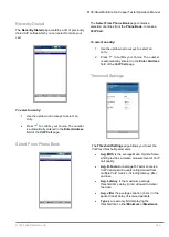
To view the 

Channel Analysis

, press 

 from the 

IPTV Summary 

tab. 


Channel Analysis 


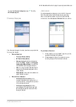
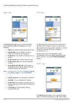
The Channel Analysis function provides a separate tab 
for every live stream  


Stream Rate Info 

o


Transport Rate (kbit/s) 

o


IP Packet Rate (kbit/s) 

o


Stream Content 

lists the information 

about the 

Video

Audio

, and 

Program 

Association

/

Map Table

(s) content for 

each MPEG video analyzed stream. 

o


PID 

is a unique packet identifier that is 

assigned to the packet payload of the 
video stream. 

o


Rate (kbit/s) 

is the rate calculated of a 

given stream content. 


Stream Error Indicator 

o


TS Packet Loss Counter 

is the 

number of packets lost, with errors, or 
out of sequence, during the test period 
in the transport stream. 

o


TS Packet Loss Ratio (%) 

is the 

percentage of IP packet loss per last 
ten thousand packets received in the 
transport stream. 


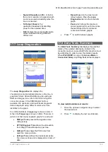
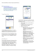
Join Leave 

The 

Join Leave 

tab displays a list of IPTV channels 

from the alias table, their activity (measured Zap 
time), and pass/fail status. Upon successful WAN 
connection, the 

Join

/

Leave Channel 

lists are shown. 


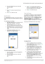
To join/leave channels: 

1.  Press 

Join 

to send an IGMP report to join the 

specified multicast IP address. 

2.  Press 

Leave

 to inform the network to stop 

sending the specified multicast stream. 


Summary of Contents for 6100-Gfast

Page 1: ...6100 Gfast Ultra Broadband Network Analyser and Copper Tester Operation manual 90 6100 GFAST OPMAN ENG 01 ...

Page 2: ...6100 Gfast Multifunction Network Analyzer Operation Manual 2 2020 Radiodetection Ltd inside front cover ...

Page 3: ...8 Test Lead Compensation 44 7 9 FED Control 44 7 10 Saving Results 49 Reading Saved Copper Test Results 51 8 1 Result Manager 51 8 2 Results Summary 51 8 3 Result Manager Menu 51 8 4 Upload 54 8 5 Export 54 8 6 Delete 55 Multimeter Tests 56 9 1 Multimeter Main Page 56 9 2 Voltage 57 9 3 Current 59 9 4 Resistance 61 9 5 Resistive Balance 64 9 6 Isolation 66 9 7 Capacitance Opens 68 9 8 Station Grou...

Page 4: ...Summary 189 Saving Reading and Managing DSL IP Test Results 194 18 1 Saving Results 194 18 2 Managing Results 196 Maintenance 199 19 1 General Maintenance 199 19 2 Recalibrating the Unit 199 19 3 Battery 199 19 4 Recycling and Disposal 201 Troubleshooting 202 20 1 Solving Common Problems 202 20 2 LED Statuses 203 20 3 Transportation 204 Software License Agreement Agreement 205 21 1 DEFINITIONS 205...

Page 5: ...ow your company and national safety procedures and or requirements when operating this equipment in any environment or workplace If you are unsure what policies or procedures apply contact your company or site s occupational health and safety officer or your local government for more information Do not use this equipment if you suspect that any component or accessory is damaged or faulty Use autho...

Page 6: ...hich makes it ideal for field use Its display is a back lit LCD featuring 480 x 800 resolution A membrane keypad mounted on the face of the unit features a 14 button keypad used to operate the test set An external keyboard and mouse can also be used 2 4 Key Features and Benefits Broadcom chipset IP login Single ended copper testing no remote device required DSL testing User defined automatic testi...

Page 7: ...ded by the equipment may be impaired The 6100 Gfast is equipped with a series of interfaces shown in the following views Fig 3 1 6100 Gfast connections left view Fig 3 2 6100 Gfast connections right view Fig 3 3 6100 Gfast connections top view Fig 3 4 6100 Gfast connections back view Note The 6100 Gfast enclosure may become warm during normal use 3 1 Cable Connections The graphics below show the c...

Page 8: ... of electrical testing of common telephone line conductors within the ranges specified in the Technical Specifications found on the Radiodetection Web site The device is not intended to be used on telephone lines having voltages greater than 280 VAC or 400 VDC and it is also not intended to be used on power distribution circuits CAUTION The unit is protected against damage caused by fault voltages...

Page 9: ...oors Only use with a Class II AC DC adapter power limited output On the AC DC adapter replacing detachable mains supply cords with inadequately rated cords may result in overheating of the cord and create a fire risk The adapter shall have the appropriate safety mark e g UL CSA TUV CE etc that is acceptable to the authorities in the country where the equipment is to be used CAUTION When using the ...

Page 10: ...ically shut down This prevents complete battery discharge and ensures maximum battery performance To perform a shutdown Hold down for at least 4 seconds The shutdown process starts Note In both previous cases if the power adapter is connected the 6100 Gfast will simulate either a fake suspend or fake shutdown in order to facilitate the charger Note If you hold down for 12 seconds or more the 6100 ...

Page 11: ... second Note The date and time value format is dependent on the format selected in System Settings Date and Time Screenshots can be Enabled or Disabled from the System Settings Display and Language page If Enabled press and hold the key to capture a screenshot on any page A popup message is displayed saying Screenshot captured Press Yes to save or No to continue to Help Pressing No will also disca...

Page 12: ...stem Settings System Settings presents a menu of items to setup the unit Display and Language provides the setup for backlight information on the title bar language choice and Touchscreen Calibration Date and Time sets the date time and format Battery Info displays the battery status and measurements and allows you to set the power schemes Software Options allow you to enable disable purchased fea...

Page 13: ...00 Screenshots on the USB memory device If the directory does not exist create it on the root directory of the USB memory device Note If you selected USB as the screenshot file location and no USB is connected to the 6100 Gfast the following popup message is displayed Screenshot not saved Insert USB and press Yes to save it or press No to continue to Help o If FTP the image is saved locally to DAT...

Page 14: ...e only a Radiodetection certified Bluetooth dongle To initiate remote display 1 Connect the Bluetooth Dongle or USB Connection to a USB port on the 6100 Gfast 2 Select the Connect to Device and press the up arrow key to highlight and press the Enable Remote Display button OR 3 Press the down arrow key to highlight and press the Find Bluetooth Devices button to search for available Bluetooth device...

Page 15: ...you can wake up the system by pressing Note If you hold down for 12 seconds or more the 6100 Gfast may reset the date and time to incorrect values Once the unit is powered back on an Invalid Date and Time dialog box will pop up displaying The unit date and time are probably invalid 1 1 2006 12 00 25 PM Please update the date and time in System Settings Date and Time to ensure the delivery of all t...

Page 16: ...hen press to confirm the choice Repeat for the other modes as needed 6 7 Software Options To activate a newly purchased option key on your 6100 Gfast please contact Radiodetection The unit may require returning to Radiodetection DSL Options This screen lists all the DSL Configured Options that are present on the unit Possible options are as follows VDSL2MOD Support VDSL2 test PING Support Ping and...

Page 17: ...e options are FTP Result Upload Touchscreen Support always enabled Wi Fi Test 6 8 Information About Radiodetection The About tab contains contact information should you require technical assistance 6100 Gfast Information The Information tab displays information about the product software and memory installed on the device The page also identifies hardware information To view the complete version n...

Page 18: ...tus is indicated as follows o Green icon indicates that the 6100 Gfast is connected with a Wi Fi hotspot o Yellow icon indicates that the Wi Fi dongle is powered up and ok but that the 6100 Gfast is not connected to any Wi Fi hotspot o Red icon indicates a problem with the Wi Fi dongle not attached etc Ethernet is the default upload and if selected displays an Ethernet icon in the top right hand c...

Page 19: ...rows to select the desired parameter 2 Press the left right arrow keys to view and select the options OR 3 Press on a value to open a list box of options or the alphanumeric editor screen and use the navigation keys to scroll through 4 Press to confirm the value Wi Fi Setup The Wi Fi Setup pages allows you to connect your 6100 Gfast to a Wi Fi network Select a Wi Fi Network for Upload lists the av...

Page 20: ...he name of the desired Wi Fi network Security lists the following wireless security protocols o WEP Wired Equivalent Privacy o WPA Wi Fi Protected Access o WPA2 Wi Fi Protected Access version 2 Note When using WPA encryption some specific routers may have performance issues with the supplied Wi Fi dongle In this case please use WPA2 encryption Password opens the alphanumeric editor screen allowing...

Page 21: ...the address for the unit that is actively connected to your network or the internet at the time of login o Gateway is the IP address of the default gateway o Subnet Mask is the network address used to identify if the IP address is within the same wide area network o DNS1 is the address of the primary domain name server to be used by the unit If DNS is unavailable enter 0 0 0 0 o DNS2 is the addres...

Page 22: ...on and authentication types NONE WEP OPEN WEP SHARED WPA TKIP WPAPSK TKIP WPA2 TKIP WPA2PSK TKIP WPA AES WPAPSK AES WPA2 AES WPA2PSK AES Network Type is either Access Point the infrastructure network or router or Adhoc spontaneous To navigate to a Wi Fi network and view the details 1 Press to get into the list 2 Press the up down arrow keys to select a network and view its details below 6 11 Comms...

Page 23: ...tifunction Copper Tester Operation Manual 2020 Radiodetection Ltd 23 Ethernet Setup The Ethernet Setup function for Comms Setup is the same as in the System Settings Upload Setup Please see Ethernet Setup on page 21 ...

Page 24: ...Test Configuration menu provides the utilities to setup test parameters The 6100 Gfast supports several types of copper test applications Test parameters and thresholds are saved into a test configuration profile A Profile Default is provided with a predefined set of parameters for all test applications Note Cable parameters are not included in these profiles but can be configured in Setup Select ...

Page 25: ...e o Save As opens the alphanumeric editor screen allowing you to enter a new name for the profile selected o Don t Save deletes the message box without saving the changes to the currently selected profile To navigate between the configuration icons 1 Press the up down left right arrow keys on the keypad to select an icon 2 Press to confirm your selection Select Profile The Select Profile page list...

Page 26: ...ests Voltage Current Resistance Resistive Balance Isolation Capacitance Opens Station Ground Stressed Balance To navigate between the test profiles 1 Press the up down left right arrow keys on the keypad to select an icon 2 Press to confirm your selection Noise Tests Profile Details The profile details Noise Tests main menu allows you to view the test threshold and parameters of the following test...

Page 27: ...right arrow keys on the keypad to select an icon 2 Press to confirm your selection TDR Profile Details The profile details TDR menu allows you to select and view the parameters set for the following tests Auto TDR Manual TDR xTalk TDR To navigate between the test profiles 1 Press the left right arrow keys on the keypad to select an icon 2 Press to confirm your selection Auto Test Profile Details T...

Page 28: ...the Setup function 1 On the Home pane highlight Copper Test then press 2 From the Copper Main page select Setup and press Setup presents a menu of items to set up copper tests Phone Book includes pages to setup and save groups of phone numbers Cable Book includes pages to select add clone and delete a cable as well as modify its details Application Settings include the following pages General Stan...

Page 29: ...tion Select Group Entry The page lists entries by Group ID and Entry Name Type There is 1 group of 3 factory default entries which cannot be edited or deleted The Phone Book can include a maximum of 50 groups Group in use displays the group number in use To select a group and entry 1 Press the up down arrow keys to highlight the desired entry and press The Group in Use is updated with the current ...

Page 30: ... Accept function key to update the Phone Book with your changes Add Group The Add Group page allows you to add a new group entry into the Phone Book using the following parameters for the currently highlighted Group ID Group ID displays the group ID number This parameter cannot be modified Entry Name is the name of the entry in the Phone Book Phone Number is the 10 digit numeric phone number of th...

Page 31: ...plays the group number in use To delete a group entry 1 Press the up down arrow keys to select the entry to be removed 2 Press the Delete function key to remove the selected entry from the Phone Book If you try to delete a cable in use a warning message pops up and changes the Group in Use to Group 1 by default OR 3 Press to cancel your selection remove any display message and go back without impa...

Page 32: ...ts the save destinations o 6100 Gfast internal memory o USB Save button saves the selected file Note The unit will overwrite any document with the same file name found on the disk without warning To save a phone book 1 Accept the default file name or press to create a new one using the edit screen 2 Select a Storage Location 3 Press Save 7 5 Dialer Function The Dialer function provides a dial up p...

Page 33: ...ommands Allows you to use the unit as a telephone with the built in speaker or external headset and the on screen phone keypad as a dialer when Enter Number is invoked whether in the test results screens or through the separate dedicated Dialer application The following parameters can be accessed from this page Dialing Status shows the current status of the dialed number Group ID displays the grou...

Page 34: ...ing For example pressing Pause consecutively 3 times creates a 3 second pause 3 Move left or right in the text box by using Cursor Left Right function keys 4 Delete a character by moving the cursor to the left of the character and pressing the Delete function key 5 Press Done function key when you have completed entering a phone number Note Alphabets on the keypad are for reference only Pressing a...

Page 35: ...the name of the entry in the Phone Book Phone Number is the 10 digit numeric phone number of the entry Type displays the following list of values o Milliwatt tone o Drop battery o Quiet line o for additional line types Enable displays either Yes or No Add function key adds the new group entry to the Phone Book To add a number to the phone book 1 Press the up down arrow keys to highlight the desire...

Page 36: ...ying Cable Details OR 2 Press to cancel your selection and go back to the Cable Book menu Cable Details The Cable Details page allows you to view the parameter details of the Cable in Use or select a Cable ID number by pressing the left right arrow keys on the keypad and view its details You can only modify cables from the CableBookSettings book see above Cable Name is the name of the cable in the...

Page 37: ...ing wire sizes in AWG American Wire Gauge0 units or mm metric wire size Cable Fill allows you to select the type of material the cable can be filled with Aircore Jelly Pulp 5 PR or 2 PR Capacitance T R A B allows you to specify a value for the capacitance per length constant Capacitance T R to GND A B to E allows you to specify a value for the capacitance per length to ground constant Resistance a...

Page 38: ... back to the Cable Book menu Delete Cable The Delete Cable page allows you to delete a cable entry from the selected Custom Cable Book The page lists all entries by Cable ID Cable Name and Cable Fill Cable in Use displays the ID number of the cable in use Cable Book Version displays the current edition number of the Cable Book in use To delete a cable entry 1 Press the up down arrow keys to highli...

Page 39: ...OR 5 Press Cancel to remove the message Save Cable Book The Save Cable Book page allows you to save or export a cable book Save File allows you to enter a file name of the current cable book to save By default the name is cable_book csv The Storage Location lists the save destinations o 6100 Gfast internal memory o USB Save button saves the selected file Note The unit will overwrite any document w...

Page 40: ...n effect and is applied to TDR WB Attenuation and FaultMapper tests Test Startup Mode lists the test startup type o Auto default automatically starts a test when you select the respective icon from the test sub menu pane and press o Manual requires that you press Start Stop on the 6100 Gfast keypad to start a test Report File Storage Location is USB which is automatically selected Report Format is...

Page 41: ... units to measure the noise energy at a point in a noise spectrum Units are dependent on the previously selected Level o Cable Gauge Unit allows you to select either AWG or mm wire gauge AWG is the default for ANSI and mm for ITU If you select AWG only AWG cables will be displayed in the Cable Book Select Cable list and test pages o NTD Network Terminal Device Provider allows you to filter out cer...

Page 42: ...and Test To List Setup pages allow you to manage the entries of the list However there are 5 entries by default which cannot be edited or deleted These are DSLAM NID CPE CROSSBOX and FRAME When any of these are selected the Delete and Accept buttons are disabled A maximum of 20 different entries can be added To manage the list 1 Press the left right arrow keys to select the Previous Next Entry but...

Page 43: ... to open a list box of options 4 Press the up down arrow keys to select the option and press to confirm your selection Change Order Change Order page allows you to change the order of the File Name Fields in the list To change the order 1 Press to get into the list 2 Use the up down arrow keys to select the desired entry 3 Press to come out of the list 4 Press the up or down arrow key to activate ...

Page 44: ...nce test lead characteristics have some impact on copper test results mainly resistance capacitance and TDR tests Test lead characteristics vary with respect to cable temperature Refer to Cable Connections on page 9 on how to connect the leads before starting compensation The Test Lead Compensation routine also performs resistance and capacitance compensation The page displays the Pass Fail status...

Page 45: ...eled Pair1 Cu connectors on the FED customer side and the network side T R A B to the red labeled Pair1 Ex CO connectors towards the CO Exchange 2 For Open connect the T R A B and ground wires to the customer side of the FED blue labeled connectors 3 For T R G A B E Shorted connect the T R G A B E to the customer connectors blue labeled Pair1 Cu and the ground lead to the network ground Note P U T...

Page 46: ...r the time of the current session If you leave the copper application at next startup FED will be set to the value saved in the profile Disabled or Auto Manual Setup includes 5 options o Open 0 o T R A B Shorted 1 o T R G A B E Shorted 2 o Pass Through Exchange Connect 3 default o ID Tone 4 Set FED button activates the state defined in the Manual Setup control Test Status displays a communication ...

Page 47: ...o highlight the desired parameter 2 Press the left right arrow keys to view and select the options OR 3 Press on a value to open a list box of options and press the up down arrow keys to highlight the desired parameter 4 Press to confirm the value Noise The Noise tab allows you to set the FED States for all noise tests and lists the default value for NEXT test The Terminated FED state appends the ...

Page 48: ...Press the left right arrow keys to view and select the options OR 3 Press on a value to open a list box of options and press the up down arrow keys to highlight the desired parameter 4 Press to confirm the value Other The Other tab displays the default FED States set for all other tests The FED States are listed for the following tests xTalk TDR RFL Single Separate Good Pair K Test Pair Detective ...

Page 49: ...create edit a unique identifier for the circuit under test o Comments allows you to add any relevant information Save Result o Select Result File button displays a list of existing file names where you can save your results o Result File Storage Location gives you the option of storing results either in the 6100 Gfast internal memory or USB device The default selection comes from Application Setti...

Page 50: ...own arrow key to highlight the desired value OR 4 Press the left arrow key to erase the existing value and then use the alphanumeric keypad to enter a value To cancel the entry press 5 Press to accept the value Select Result File Select Result File page displays a list of existing file names where you can save your results To save your results to an existing File Name 1 Use the up down navigation ...

Page 51: ...lts 1 Press the left right arrow keys to highlight the desired Storage Location OR 2 Press to display the list and select the value 3 Press the down arrow key to highlight the list box and press to open the list 4 In the list press the up down arrows to select the test results file 5 Press to open the result file 8 3 Result Manager Menu The Result Manager menu allows you to view saved test results...

Page 52: ...o Contractor Name o Test From To o Job ID o Customer Name o Circuit ID o Comments Function keys o Save keeps any current changes with the current file name o Save As saves the current changes under a different file name that you can configure in the editor screen o Don t Save does not save any changes and closes the page o Report allows you to load a result file to a USB device update the ID field...

Page 53: ...tain the following entries Profile Name only displayed in Results Manager is the file name of the selected saved results Test Group is the overall test group of the selected saved results file for example Multimeter Test Identification is the test type of the group for example Current Phone Book The Phone Book page summarizes the Phone Book details when loading a results file It contains informati...

Page 54: ...ved User Auto Test results 1 Press the left right arrow keys to highlight the desired Upload Location OR 2 Press to display the list and select the value 3 Press the down arrow key and select either None or All files 4 If None press the down arrow key to highlight the list box and press to open the list 5 In the list press the up down arrows to select the desired files 6 Press to come out of the l...

Page 55: ...port Format 8 Press the left right arrow keys to select the desired format OR 9 Press to display the list and select the value 10 Press the down arrow key to press the Export button 8 6 Delete The Delete page allows you to delete a selected File Name or All selected result files previously saved in the 6100 Gfast internal memory only Storage Location is the 6100 Gfast internal memory Select Files ...

Page 56: ...ic loop continuity balance loop quality with resistance measurements measure total electrical length with capacitance measure the ground path resistance with the station ground test run a stress test Pair Detective runs many of these tests automatically and is a recommended starting test to assess loop quality and identify common faults To access Pair Detective from Multimeter tests 1 Press to ret...

Page 57: ...48 to 52 volts would indicate working POTS If you have not already done so press and select Pair Detective to identify metallic faults or even wetness The Voltage test defaults to the Continuous DC page from the Multimeter menu This function measures each pair displaying and updating results in real time until you stop the test The last valid results then remain displayed If the DC value is fluctu...

Page 58: ... each pair displaying and updating results in real time until you stop the test The last valid results then remain displayed The Voltage test defaults to the Continuous DC page from the Multimeter menu Continuous AC and Continuous DC are run synchronously Press Start Stop on the keypad to run the test Current Group is the current test group name for example Multimeter Current Test displays the tes...

Page 59: ...l status volts and frequency Hz values for each continuous AC DC pair Test Status displays the current state of measurement or an error message To select the parameter values 1 Press the up down arrow keys to highlight the desired parameter 2 Press the left right arrow keys to view and select the options OR 3 Press on a value to open a list box of options 4 Press to confirm the value 9 3 Current T...

Page 60: ...use as an on screen indicator in each test when a measured value is too high or too low Type is the threshold limit for each pair either Maximum or Minimum Enabled is a flag to use the current threshold either Yes or No To set threshold values 1 Press the up down arrow keys to highlight the desired parameter 2 Press the left right arrow keys to view and select the options OR 3 Press on a value to ...

Page 61: ...s Start Stop on the keypad to run the test Current Group is the current test group name for example Multimeter Current Test displays the test being measured Here you can switch to another test from the given list However this action will terminate the ongoing measurement test Selected Pair allows you to select All Pairs or a single wire pair for measurement Termination Resistance is a read only va...

Page 62: ...primary way to locate a one sided series fault In some cases a TDR may reflect off such a fault but then again may not Try TDR first but be prepared to try RFL if you really need this pair in service for a high speed broadband To select either TDR or RFL tests 1 Press to return to the Copper Main menu 2 Highlight TDR or RFL and press to launch the test Snapshot The resistance Snapshot shows measur...

Page 63: ...red parameter 2 Press the left right arrow keys to view and select the options OR 3 Press on a value to open a list box of options or the alphanumeric editor screen and use the navigation keys to scroll through 4 Press to confirm the value Continuous The Continuous function measures each pair displaying and updating results in real time until you stop the test The last valid results then remain di...

Page 64: ...h s TS 125 FED Far End Device can automatically set the far end condition Snapshot The Resistive Balance test is valuable in understanding the presence of resistive faults on one side versus the other series resistance A 5 difference in the Ohms value between T A and R B is common 95 balance but for higher speed DSL such as VDSL2 imbalance is more critical and should be 2 3 when possible 97 98 bal...

Page 65: ...es or No To set threshold values 1 Press the up down arrow keys to highlight the desired parameter 2 Press the left right arrow keys to view and select the options OR 3 Press on a value to open a list box of options or the alphanumeric editor screen and use the navigation keys to scroll through 4 Press to confirm the value Result Details The Results Details read only page displays the Resistance r...

Page 66: ...displays the test being measured Here you can switch to another test from the given list However this action will terminate the ongoing measurement test Selected Pair allows you to select All Pairs or a single wire pair for measurement Soak Voltage allows you to apply a voltage value to the pair s currently under test If your unit has the HIVOLT high voltage software option configured the Soak Vol...

Page 67: ...FED Control option is enabled due to its limitation the Continuous function will act the same as the test in Snapshot mode and terminate after the Soak Time period expires Current Group is the current test group name for example Multimeter Current Test displays the test being measured Here you can switch to another test from the given list However this action will terminate the ongoing measurement...

Page 68: ...ernet and better for high speed broadband such as VDSL2 If the opens distance is significantly less than indicated on plant maps then the pair may be open at the distance suggested Of course if the distance matches the expected length you are seeing the end Be a bit cautious with capacitance opens as wet faults or physical damage can significantly change the result Wetness can provide a path to gr...

Page 69: ... view and select the options OR 3 Press on a value to open a list box of options and use the navigation keys to scroll through 4 Press to confirm the value Continuous The Continuous function measures each pair displaying and updating results in real time until you stop the test The last valid results then remain displayed Significant fluctuations in the capacitance results length could indicate in...

Page 70: ...ow POTS and internet circuits should be 95 and higher speed broadband circuits 97 or 98 if possible Type is the threshold limit for each pair either Maximum or Minimum Enabled is a flag to use the current threshold either Yes or No To select the threshold values 1 Press the up down arrow keys to highlight the desired parameter 2 Press the left right arrow keys to view and select the options OR 3 P...

Page 71: ...gs button opens a new page that allows you to set the Ground Resistance Threshold for the test Show hookup diagram on test setup If Yes the Confirmation page is prompted before every Station Ground test is started Select No to hide the diagram next time you run the test Hookup Diagram button opens a Confirmation page displaying how to connect your leads at the beginning of the test The hookup diag...

Page 72: ... current threshold either Yes or No To set threshold values 1 Press the up down arrow keys to highlight the desired parameter 2 Press the left right arrow keys to view and select the options OR 3 Press on a value to open a list box of options or the alphanumeric editor screen and use the navigation keys to scroll through 4 Press to confirm the value Result Details The Result Details read only page...

Page 73: ...pear again when more moisture works its way back into the fault When you have a poor stress value 25 the next best step is to isolate the imbalance by running the Pair Detective test To access Pair Detective from Multimeter tests 1 Press to return to the Copper Main menu 2 Highlight Pair Detective and press to launch the test 3 Open the far end and see that faults are identified 4 Check the Pair D...

Page 74: ... as an on screen indicator in each test when a measured value is too high or too low Type is the threshold limit and is fixed to Maximum Enabled is a flag to use the current threshold either Yes or No Note Disabling Good Balance will also disable the Marginal Balance threshold even if you Enabled it To set threshold values 1 Press the up down arrow keys to highlight the desired parameter 2 Press t...

Page 75: ...ceed with the test Summary The Summary page displays a summary of the pass fail status DC Voltage Current and Isolation for each selected inactive wire pair as well as other detailed results of the Pair Detective test Plain language results are displayed as the test progresses with color coding to draw attention to faults You may view raw results by selecting the Multimeter tab at the bottom of th...

Page 76: ... that allows you to set the Cable Parameters for the test Threshold Settings button opens a new page that allows you to set the threshold parameters They control when Pair Detective identifies a fault such as 4 VDC for a battery fault You can also modify when Pair Detective identifies a high resistive versus normal fault by changing the threshold parameters Note Individual test parameters can be m...

Page 77: ...d Settings The Threshold Settings page allows you to set the threshold parameters for the tests below Modifying these values will change what color is used on a result and when a fault is identified such as a short at 3 5 M Ohms Foreign DC Voltage sets the maximum foreign DC voltage value Default is 4 V which is fine for POTS and internet circuits consider a lower value for a high speed DSL such a...

Page 78: ...u may continue to use the TDR test to further locate faults on the line The TDR test displays the line trace and is continuously on and ready to use It displays and updates results in real time in either Portrait or Landscape Mode recommended until you stop the test The last valid results then remain displayed Current Test displays the test being measured Range allows you to set the range from the...

Page 79: ...esult displays the distance to the most significant reflection in text and graphical measurements The distance Δ Delta value between cursor and marker is also displayed at the top of the graph Test Status displays the current state of measurement or an error message To select the parameter values in Portrait Mode 1 Press the up down arrow keys to highlight the desired parameter 2 Press the left ri...

Page 80: ... the ID Cable Name and Fill with its associated parameters from the current Cable Book used for testing Cable Fill is the type of material the cable is filled with Aircore Jelly Pulp 5 PR or 2 PR Velocity of Propagation is the velocity of propagation for the cable Cable Temperature is the temperature of the cable under test in either F or C Result displays a Summary of the overall pass fail status...

Page 81: ...gnal analysis FaultMapper can identify and or locate the following Shorts Grounds strap required to determine distance Opens Detect load coils Bridged tap The FaultMapper page displays the following parameters Current Test displays the test being measured Far End Strap allows you to select option Yes or No for use of a strap A strap while not required enables FaultMapper to calculate distance to a...

Page 82: ...of Capacitance Opens and Resistance measurements and the TDR cursor distance indication Cable Type displays the ID Cable Name and Fill and allows you to select an entry with its associated parameters from the current Cable Book to use for testing The selection is not saved when leaving the test The current Cable Book entry is shown by default Cable Gauge identifies the gauge system for measuring w...

Page 83: ...r information on this test FaultMapper Result Details The Result Details read only page displays the test results in text and graphical format Test Identification is the name of the test for example FaultMapper Cable Setup button opens a new page displaying the cable parameters of the test Use the left right arrows to select the button and press to open the page Result displays the cable fault det...

Page 84: ... T R to GND A B to E is the value for the capacitance per length to ground constant Attenuation 300 kHz is the value for the reduction in signal strength or insertion loss of the cable Velocity of Propagation is the velocity of propagation for the cable Resistance is the value for the resistance constant of the cable Cable Length is the length of the cable set to provide more accurate results Cabl...

Page 85: ...e Copper Main pane highlight Noise Tests and press to open the menu 11 1 Noise Tests Main Page The Noise Tests menu allows you to select and run the displayed tests VF Noise Power Influence VF Impulse Noise WB PSD Noise WB Impulse Noise NEXT To start stop a test 1 Press the up down left right arrow keys on the keypad to select the desired test icon 2 Press to confirm your selection 3 The test will...

Page 86: ...se threshold Result displays the pass fail status and VF Noise value Test Status displays the current state of measurement or an error message Note The selected VF Noise Filter shown in addition to the current Level units selected in Setup Application Settings have an influence on the measurement units displayed on this page To select the parameter values 1 Press the up down arrow keys to highligh...

Page 87: ...6100 Gfast Multifunction Copper Tester Operation Manual 2020 Radiodetection Ltd 87 ...

Page 88: ...ed on frequency selected in Setup Application Settings Standard Threshold Settings button opens a new page that allows you to set the power influence thresholds Select Graph button changes to Graph Selected when pressed and opens a new selection of function keys which allow you to maneuver the graph as follows o Cursor press the left right arrow keys to decrease increase the values by moving the c...

Page 89: ...open a list box of options or the alphanumeric editor screen and use the navigation keys to scroll through 4 Press to confirm the value Result Details The Result Details page displays the Power Influence value and graph and the pass fail status You can maneuver the graph as follows Cursor press the left right arrow keys to decrease increase the values by moving the cursor Press and hold the left r...

Page 90: ... is limited to15 min Threshold Settings button opens a new page that allows you to set the VF impulse noise thresholds Result displays the High Mid Low counts respective detection levels and Elapsed Time The pass fail status of the Mid level is displayed after 1 s and then periodically refreshed until you stop the test Test Status displays the current state of measurement or an error message To se...

Page 91: ... measured Here you can switch to another test from the given list However this action will terminate the ongoing measurement test Bandwidth allows you to select the frequency range for the test from a list of available bandwidths ISDN HDSL SHDSL ADSL1 2 ADSL2 VDSL2 8 VDSL2 12 VDSL2 17 VDSL2 30 or VDSL2 35 Noise Filter defines the filter currently enabled Options are None ISDN E HDSL F ADSL G ADSL ...

Page 92: ... hold o Max PSD reading among all frequency bins for the Current results o Frequency bin where Max PSD for the Current results are detected o RMS Noise reading for the Current results including a pass fail status If Peak Hold is ON o Max PSD Peak reading among all frequency bins o Frequency bin for Max PSD Peak Test Status displays the current state of measurement or an error message To select the...

Page 93: ...lect one or more Masks or All DPBO Downstream Power Back Off is either ON or OFF ESEL Exchange Side Electrical Length is used to enter or modify the numerical values of attenuation of the cable at 1 MHz frequency from 0 to 120 dB with one decimal point This represents the DPBOESEL variable or electrical length of exchange to cabinet cable and is applied to the DPBO mask calculation Note DPBO and E...

Page 94: ... out Pan use left right arrow keys to pan the x axis and the up down arrow keys to pan the y axis 1 1 resets the x axis and y axis limits to full scale Landscape Mode function key allows you to view the test results in landscape mode Whether the keyboard is on the right or left is dependent on your preferred Landscape Mode Settings configured in Setup Application Settings General Portrait Mode is ...

Page 95: ...r an error message To select the parameter values 1 Press the up down arrow keys to highlight the desired parameter 2 Press the left right arrow keys to view and select the options OR 3 Press on a value to open a list box of options or the alphanumeric editor screen and use the navigation keys to scroll through 4 Press to confirm the value WB Impulse Noise Threshold Settings The Threshold Settings...

Page 96: ...Right x axis zoom in o Left x axis zoom out o Up y axis zoom in o Down y axis zoom out Pan use left right arrow keys to pan the x axis and the up down arrow keys to pan the y axis 1 1 resets the x axis and y axis limits to full scale Return To Test removes these function keys and displays the previous ones Result Details Count The Results Details read only page displays the WB Impulse Noise Count ...

Page 97: ...aying how to connect your cables at the beginning of the test When FED is Enabled on the FED Setup page both the T R A B and T1 R1 A1 B1 pairs will be terminated at the FED The hookup diagram uses graphic and textual components o Proceed button closes the hookup diagram prompt and starts the test o Cancel button closes the hookup diagram prompt only o The Confirmation window is prompted before eve...

Page 98: ...To set threshold values 1 Press the up down arrow keys to highlight the desired parameter 2 Press the left right arrow keys to view and select the options OR 3 Press on a value to open a list box of options or the alphanumeric editor screen and use the navigation keys to scroll through 4 Press to confirm the value Spot Result Details The Spot Results Details read only page displays the saved pass ...

Page 99: ...ram at any time by pressing the Hookup Diagram button In this case the test does not start when you press the OK button to close the Confirmation window Threshold Settings button opens a new page that allows you to set the NEXT Spectrum Threshold Select Graph button changes to Graph Selected when pressed and opens a new selection of function keys which allow you to maneuver the graph as follows o ...

Page 100: ...pen a list box of options or the alphanumeric editor screen and use the navigation keys to scroll through 4 Press to confirm the value Spectrum Result Details The Spectrum Results Details read only page displays the pass fail status and test results in graphical format Test Group is the overall test group of the selected saved results file for example Noise Tests Test Identification is the test ty...

Page 101: ... Test removes these function keys and returns to the Spectrum results page NEXT Results Profile Details The NEXT Profile Details page displays detailed read only test thresholds and parameters for both Spot and Spectrum modes Profile Name is the file name of the selected saved results Test Group is the overall test group of the selected saved results file for example Noise Tests Test Identificatio...

Page 102: ... to confirm your selection 3 The test will start automatically if the Setup Application Settings General Test Startup Mode is set to Auto If not press Start Stop on the keypad 12 2 VF AC Balance The VF AC Balance test allows you to check that the VF longitudinal balance ratio for the twisted pair complies with applicable standards so as to reduce the effects of common mode voltage to ground The te...

Page 103: ...rameter 2 Press the left right arrow keys to view and select the options OR 3 Press on a value to open a list box of options 4 Press to confirm the value VF AC Balance Active Threshold Settings The Threshold Settings page allows you to set the Active VF AC Balance Threshold values for the test VF AC Balance sets the active balance threshold Type is the threshold limit either Maximum or Minimum Ena...

Page 104: ...ement test Noise Filter displays the type of noise filter used Power Line Frequency displays the frequency value of the power line Threshold Settings button opens a new page that allows you to set the VF AC Balance Threshold Result displays the Passive pass fail status Power Influence VF Noise and VF AC Balance values Test Status displays the current state of measurement or an error message Note T...

Page 105: ...ic editor screen and use the navigation keys to scroll through 4 Press to confirm the value Passive Result Details The Passive Results Details read only page displays the Passive pass fail status Power Influence VF Noise and VF AC Balance values 12 3 WB Balance The wideband balance test ensures that the balance ratio for the twisted pair complies with applicable standards so as to reduce the effec...

Page 106: ...e Marginal and Good balance results and pass fail status If any attenuation measurement trace is greater less than the corresponding marginal test threshold for a maximum minimum threshold the status is fail Otherwise the status is pass o Good is the good balance threshold for the currently selected bandwidth represented by a horizontal green line o Marginal is the marginal balance threshold for t...

Page 107: ...isting threshold either Yes or No For example setting the threshold Enabled to No will disable pass fail threshold Mask Tolerance allows you to set a marginal pass value which will be displayed on the graph in yellow To set threshold values 1 Press the up down arrow keys to highlight the desired parameter 2 Press the left right arrow keys to view and select the options OR 3 Press on a value to ope...

Page 108: ...inal pass value which will be displayed on the graph in yellow Threshold Frequency allows you to add threshold calculations to the WB Attenuation test by selecting a technology that is used for threshold pass fail estimation The list of technologies is dynamically populated based on the selected Bandwidth Whenever you change the Bandwidth the Threshold Frequency is set to the default None Threshol...

Page 109: ... message To select the parameter values 1 Press the up down arrow keys to highlight the desired parameter 2 Press the left right arrow keys to view and select the options OR 3 Press on a value to open a list box of options or the alphanumeric editor screen and use the navigation keys to scroll through 4 Press to confirm the value WB Attenuation Threshold Settings The Threshold Settings page allows...

Page 110: ...he total length for all cable sections cannot exceed 8000 m or 24000 ft If you do not enter a length for each section selected the total equivalent attenuation cannot be calculated Cable Attenuation Data is set to Yes for each cable section selected To select the parameter values 1 Press the up down arrow keys to highlight the desired parameter 2 Press the left right arrow keys to view and select ...

Page 111: ...e Good is the good balance threshold mask for the currently selected bandwidth represented by green in the graph Result Details Cable Configuration The Cable Configuration page in the Results Details allows you to view the cable parameters set for the WB Attenuation test No of Cable Sections is the number of consecutive cable sections with a maximum of 4 Cable Type displays the number of a cable s...

Page 112: ...wn arrow keys to highlight the desired parameter 2 Press the left right arrow keys to view and select the options OR 3 Press on a value to open a list box of options or the alphanumeric editor screen and use the navigation keys to scroll through 4 Press to confirm the value Return Loss Threshold Settings The Return Loss Threshold Settings page allows you to set the Loss Threshold for each pair The...

Page 113: ... selection of function keys which allow you to maneuver the graph as follows o Cursor press the left right arrow keys to decrease increase the values by moving the cursor Press and hold the left right arrow keys to accelerate the cursor Press to recall the cursor and place it in the middle of the current x axis limits o Zoom references the middle of the x y axis and not the cursor position Press t...

Page 114: ...tting the threshold Enabled to No will disable pass fail threshold Mask Tolerance is a fixed value representing a marginal pass area on the graph shown in yellow To set threshold values 1 Press the up down arrow keys to highlight the desired parameter 2 Press the left right arrow keys to view and select the options OR 3 Press on a value to open a list box of options or the alphanumeric editor scre...

Page 115: ...t allows you to detect the presence of load coils which are detrimental to the use of DSL technologies on the line If a load coil is detected use the TDR time domain reflectometer test to quickly locate and remove it from the cable Detection The Detection function specifies the presence or absence of load coil in the cable section and displays the number of load coils in the line and measured valu...

Page 116: ... these function keys and displays the Detection page Result displays the number of load coils in text and graphical format Test Status displays the current state of measurement or an error message To select the parameter values 1 Press the up down arrow keys to highlight the desired parameter 2 Press the left right arrow keys to view and select the options OR 3 Press on a value to open a list box ...

Page 117: ...to locate 983 Hz Tone The Tone function allows you to set the Tone Power and generate a pulsed tone on the line to trace a cable pair at the far end Current Group is the current test group name for example Frequency Tests Current Test displays the test being measured Here you can switch to another test from the given list However this action will terminate the ongoing measurement test Tone Power a...

Page 118: ...el and VF WB Frequency Test Status displays the current state of measurement or an error message To select the parameter values 1 Press the up down arrow keys to highlight the desired parameter 2 Press the left right arrow keys to view and select the options OR 3 Press on a value to open a list box of options or the alphanumeric editor screen and use the navigation keys to scroll through 4 Press t...

Page 119: ...ys the saved receive tone or RX VF WB Level and VF WB Frequency values Profile Details Receive Tone The Profile Details page displays read only Receive Tone Test Parameters Tone displays whether the receive tone was VF or WB Termination Resistance is the resistance value selected for the termination of the Receive Tone test 12 9 RX Tone with FED The RX Tone with FED test can be setup to run a sing...

Page 120: ... only value of 600 Ω o for WB Tone select 100 120 or 135 Ω FED Frequency sets the frequency that the TS125 FED will transmit and is a value in Hz for VF Receive Tone default 300 Hz and kHz for WB default 196 kHz Tone Duration modifies the duration value of the tone from 5 60 seconds Default is 5 s Result displays the values for both the RX VF WB Loss and Frequency Test Status displays the current ...

Page 121: ... 3604 Hz o for WB Receive Tone HDSL 20 30 50 70 90 110 130 196 400 kHz T1 E1 200 400 500 700 772 1024 kHz ADSL1 2 25 69 90 110 138 300 550 800 1104 2208 kHz VDSL2 12 25 138 276 3000 3750 5200 8500 12000 kHz WB 5 Tone 196 392 772 1100 2200 kHz Select Graph button changes to Graph Selected when pressed and opens a new selection of function keys which allow you to maneuver the graph as follows o Curs...

Page 122: ...oving the cursor Press and hold the left right arrow keys to accelerate the cursor Press to recall the cursor and place it in the middle of the current x axis limits o Zoom references the middle of the x y axis and not the cursor position Press the arrow keys as follows Right x axis zoom in Left x axis zoom out Up y axis zoom in Down y axis zoom out Pan use left right arrow keys to pan the x axis ...

Page 123: ...r both the Single and Multiple RX Tone with FED tests and may contain the following entries Profile Name only displayed in Results Manager is the file name of the selected saved results Test Group is the overall test group of the selected saved results file for example Frequency Tests Test Identification is the test type of the group for example RX Tone with FED ...

Page 124: ...anual TDR does not automate any function nor settings and gives you full control over TDR parameters such as Range Gain VOP and Pulse Width The test displays results in graphical format updating them in real time until you stop the test The last valid results then remain displayed 3 xTalk crosstalk TDR allows you to locate split pairs between tip A and ring B copper wires which may be causing serv...

Page 125: ...eak turns Peak Hold on and collects minimum maximum measurement values displaying all 3 traces o Peak Only turns Peak Hold on displaying only Peak traces with no offset o Live Store Diff selection is only available while the test is running and a Trace is loaded The differential trace is calculated between Live and loaded stored traces during the measurement and displayed on the graph with no offs...

Page 126: ...iew the test results in landscape mode utilizing the full length of the high resolution color screen Whether the keyboard is on the right or left is dependent on your preferred Landscape Mode Settings configured in Setup Application Settings General Landscape Mode generates the following function keys o Portrait Mode is used to change the screen orientation from landscape to portrait o Select Grap...

Page 127: ...6100 Gfast Multifunction Copper Tester Operation Manual 2020 Radiodetection Ltd 127 Examples of Common Faults Short Open Bridged Tap ...

Page 128: ...6100 Gfast Multifunction Network Analyzer Operation Manual 128 2020 Radiodetection Ltd Splice Joint Peak Function Dual Trace View ...

Page 129: ... results then remain displayed Current Group displays the test being measured Current Test allows you to select either Auto Manual or xTalk TDR Note The test has the same parameters as the Manual TDR test and does not inherit Auto TDR settings Range Gain Pulse Width when switching to the test from the Current Test setup line Range allows you to set the range from the given list Gain allows you sel...

Page 130: ...t allows you to load a trace from a list of previously saved TDR tests Clear Trace function key deletes the loaded trace from the graph To select the parameter values in Portrait Mode 1 Press the up down arrow keys to highlight the desired parameter 2 Press the left right arrow keys to view select the options or increase decrease values OR 3 Press on a value to open a list box of options or the al...

Page 131: ...able under test in either F or C To select the parameter values 1 Press the up down arrow keys to highlight the desired parameter 2 Press the left right arrow keys to view and select the options OR 3 Press on a value to open a list box of options or the alphanumeric editor screen and use the navigation keys to scroll through 4 Press to confirm the value 13 4 Load Trace The Load Trace function allo...

Page 132: ...cts minimum maximum measurement values displaying all 3 traces o Peak Only turns Peak Hold ON displaying only Peak traces with no offset Note If the loaded secondary trace offset 0 then the primary and secondary traces will overlap Cable Setup button allows you to view the Cable Parameters of the TDR test Select Graph button changes to Graph Selected when pressed and opens a new selection of funct...

Page 133: ...strip window listing the following values Range Gain Pulse Width and Current Trace not in Auto TDR They can be edited or viewed the same way as in Portrait Mode described above dependent on the TDR test being run o Cable Setup displays a small strip window when selected allowing you to view the Cable Type Cable Fill Velocity of Propagation and Cable Temperature For more information see Cable Setup...

Page 134: ... the Results Details is the same as previously described Please see Load Trace on page 131 for more information 13 6 TDR Profile Details The Profile Details page displays read only TDR Test Parameters Profile Name is the file name of the selected saved results Test Identification is the test type of the group for example TDR ...

Page 135: ... the beginning of the test The FED allows you to remotely place a strap to short together the T R A B pair at the far end for 2 wire RFL The Confirmation diagram uses graphic and textual components o Proceed button closes the hookup diagram prompt and starts the test o Cancel button closes the hookup diagram prompt only Note Results are less accurate than a separate good pair setup Current Test di...

Page 136: ...nabled on the FED Setup page the Confirmation window pops up displaying how to connect your cables at the beginning of the test The FED allows you to remotely place a strap to short together the A1 A B T1 T R at the far end for 4 wire RFL The Confirmation diagram uses graphic and textual components Proceed button closes the hookup diagram prompt and starts the test Cancel button closes the hookup ...

Page 137: ...onductors of one pair In other words the K Test is specialized for detecting double faults Due to the precision and sensitive nature of RFL tests the cable pair under test should be open disconnected and battery removed One of the faults must be greater in resistance than the fault on the other pair Note K Test is implemented to locate double sided faults when a good wire pair isn t available Both...

Page 138: ...1 and Fault 2 The larger the fault size difference the lower the open ratio number o Closed Ratio is a comparison between sections The larger the Closed Ratio value the closer the fault is to the strap end o Lx L displays a length ratio where Lx Length to fault and L total Length Based on the cable condition corresponding values are added into the diagram at their specific positions Test result un...

Page 139: ...resence of load coils to either Yes or No Cable Temperature allows you to change the temperature of the cable under test in either F or C To select the parameter values 1 Press the up down arrow keys to highlight the desired parameter 2 Press the left right arrow keys to view and select the options OR 3 Press on a value to open a list box of options or the alphanumeric editor screen and use the na...

Page 140: ...arameter 2 Press the left right arrow keys to view and select the options OR 3 Press on a value to open a list box of options or the alphanumeric editor screen and use the navigation keys to scroll through 4 Press to confirm the value 14 6 Result Details Single Pair The Results Details read only page displays the Single Pair RFL results using text and a connection diagram Test Identification displ...

Page 141: ...d a connection diagram Test Identification displays the current test for example RFL Cable Setup button opens a new page displaying the cable parameters of the RFL test Press to open the page Cable Setup The Cable Setup page displays the cable parameters for each section used while running the RFL test Settings are shared by both Single Pair and Separate Good Pair tests ...

Page 142: ...to detect the loop current and measure the voice frequency parameters in a copper telephone loop This test allows you to compare measured results against stored threshold values to provide pass or fail status results of the POTS circuit type To access POTS Auto Test 1 From the Copper Main menu use the up down left right arrow keys to highlight Auto Test and press 2 Highlight POTS Auto Test and pre...

Page 143: ...t the options OR 3 Press on a value to open a list box of options 4 Press to confirm the value POTS Auto Test Threshold Settings The Threshold Settings page allows you to set the POTS Auto Test Threshold Settings for the combination of multiple tests The threshold values do not come from individual tests but are unique to POTS Loop DC Current sets the DC current value for the wire pair Loss sets t...

Page 144: ...er Auto Test and press to start the test Summary The Summary page displays the overall pass fail status of all tests selected for auto testing Current Group is the current test group name for example Auto Test Current Test displays the test being measured Here you can switch to another test from the given list However this action will terminate the ongoing measurement test When FED is Enabled the ...

Page 145: ... under test VF Impulse Noise measures the random occurrences of energy spikes in the voice frequency range that have random amplitude and spectral content WB PSD Noise measures power spectral density noise WB Impulse Noise measures the irregular occurrences of energy spikes in the wideband range that have random amplitude and spectral content VF AC Balance Active is very useful in identifying loop...

Page 146: ...der test o Comments allow you to add any relevant information Save Result o Select Result File button displays a list of existing file names where you can save your results o Result File Storage Location gives you the option of storing results either in the 6100 Gfast internal memory or USB device The default selection comes from Application Settings General tab o Result File Name previews the res...

Page 147: ...er 1 Result page displays the following results and pass fail status AC DC Voltage volts and frequency Hz values for each continuous AC DC Pair AC DC Current DC current AC current and frequency Hz values for each wire Pair Resistance for each wire Pair and Length for T R A B Multimeter 2 Result The Multimeter 2 Result page displays the following results and pass fail status Resistive Balance R B L...

Page 148: ...ess to confirm the test Select Graph button changes to Graph Selected when pressed and opens a new selection of function keys which allow you to maneuver the graph as follows o Cursor press the left right arrow keys to decrease increase the values by moving the cursor Press and hold the left right arrow keys to accelerate the cursor Press to recall the cursor and place it in the middle of the curr...

Page 149: ...arrow keys to highlight the desired test 3 Press to confirm the test Select Graph button changes to Graph Selected when pressed and opens a new selection of function keys which allow you to maneuver the graph as follows o Cursor press the left right arrow keys to decrease increase the values by moving the cursor Press and hold the left right arrow keys to accelerate the cursor Press to recall the ...

Page 150: ...ll the cursor marker and place it in the middle of the current x axis limits o Zoom references the middle of the x y axis and not the cursor position Press the arrow keys as follows Right x axis zoom in Left x axis zoom out Up y axis zoom in Down y axis zoom out o Pan use left right arrow keys to pan the x axis and the up down arrow keys to pan the y axis o 1 1 resets the x axis and y axis limits ...

Page 151: ...late button allows you to recalculate data rates after editing the following Test Parameters o SNR Margin is the signal to noise ratio margin measured on the line o Bits Bin allows you to select the ADSL bandwidth bit rate o Technology allows you to select a frequency band from a list of possible technologies subject to the Software Options enabled Note VDSL2 35b requires the VDSL2 35b Data Rate P...

Page 152: ...he cable used in the Auto Test Press to open the page Cable Setup The Cable Setup page displays read only parameters of the cable used in the Auto Test Cable Type displays the ID Cable Name and Fill with its associated parameters from the current Cable Book used for testing Cable Fill Material is the type of material the cable is filled with Aircore Jelly Pulp 5 PR or 2 PR Velocity of Propagation ...

Page 153: ...r The Multimeter Parameters page displays the profile details of the cable parameters for all multimeter tests Noise 1 Parameter The Noise 1 Parameter page displays the profile details of the parameter values for the VF Noise Power Influence and VF Impulse Noise tests Noise 2 Parameter The Noise 2 Parameter page displays the profile details of the parameter values for the WB PSD Impulse Noise test...

Page 154: ...er 1 Threshold The Multimeter 1 Threshold page displays the AC DC Voltage and Current Test Thresholds and limits for each Pair Multimeter 2 Threshold The Multimeter 2 Threshold page displays the Test Thresholds and limits for the following tests Resistance displays values for each Pair Resistive Balance displays values for the test in Ω and Isolation displays the Resistance thresholds for each Pai...

Page 155: ...value and limit as well as the Low Counter Power and Power Threshold Separation WB PSD Noise displays the RMS Noise and limit WB Impulse Noise displays the Power Detection Level Counter threshold value and limit Frequency Threshold 1 The Frequency Threshold 1 page displays the VF AC Balance Active and WB Balance threshold values and limits Frequency Threshold 2 The Frequency Threshold 2 page displ...

Page 156: ... phone numbers relevant to performing VoIP tests 16 2 Test Configuration The 6100 Gfast supports 3 types of test applications Auto Test Manual Test and Ethernet Test Configuration parameters for all 3 test applications are saved into a test configuration profile A default profile is provided with a predefined set of parameters for all test applications Select Profile lists saved available profiles...

Page 157: ...oard 2 Press to confirm each selection 3 Use the on screen function buttons to create or edit the word Profile Details Menu You can view any of your saved profiles on the 6100 Gfast from the Profile Details menu by selecting the desired test setup icon This sub menu displays an icon for each test Auto Test Manual and Ethernet To select a test 1 Press the up down left right navigation keys to selec...

Page 158: ...is on pair 1 and ADSL Annex B and UR2 are on pair 2 This modem does not support bonding Test Interface options are as follows o G fast Pair 1 o VDSL2 ADSL2 xA Pair 1 o ADSLMulti xA Pair 1 o VDSL2 35b Pair 1 o ADSL2 xB Pair 2 o ADSLMulti xB Pair2 o ADSL2 UR2 Pair 2 o ADSLMulti UR2 Pair 2 Annex M allows you to Enable Disable this option when Test Interface is o VDSL2 ADSL2 or VDSL2 ADSL2 Bonding for...

Page 159: ...to DHCP Static or IPoA Login to WAN Data Test in Manual Test Setup only can be set to one of the following when running a Manual Test o Auto will start the WAN login automatically right after Show Time o Manual enables a Login button on the WAN Status page once Show Time is reached You must press the button to start the WAN login This parameter cannot be selected for the following Access Modes Syn...

Page 160: ... Through Mode Enable or Disable When the Access Mode is Bridged Pass Through Mode is set to Enable LAN IP Address is the local network IP address of the unit Note If the DSL WAN has an IP address on a specific subnet for example 192 168 x y and the Ethernet LAN port is enabled configure the default LAN IP address to a different subnet for example 10 0 x y to avoid IP communication problems Subnet ...

Page 161: ...arginal and acceptable rates D S and U S OK bit rate o for ADSL value limited to D S 30 Mbit s U S 2 Mbit s o for VDSL D S to 100 Mbit s U S to 50 Mbit s o for G fast D S and U S maximum value set to 1000 Mbit s o for VDSL2 35b D S can be 350 Mbit s U S is 50 Mbit s D S and U S Min SNR margin values range from 0 to 63 5 dB Default is 5 dB D S and U S Max Attenuation values range from 0 to 96 dB De...

Page 162: ...ser understand and acknowledge by performing the test contained in the Speedtest Powered Software Application that Ookla LLC may collect your IP address during the test and share it with selected third parties Traceroute is a complement tool of the Ping test to determine why a destination cannot be reached or where the internet is broken Web Browser Test can only be started when a WAN connection e...

Page 163: ...s state is detected with the message Incoming call o If Auto Answer is No then the popup presents you with the choices Answer or Decline o If Auto Answer is Yes then the popup message presented is Incoming call and persists for 5 seconds Test Duration allows you to set the duration of the VoIP test in seconds o Communication Channel is the parameter based on either UDP or TCP o Controller Setup bu...

Page 164: ...read only displays the domain name www radiodetection com To enter a user name 1 Press to open the alphanumeric editor screen and use the navigation keys to scroll through 2 Press to confirm the value Proxy Setup Proxy is the registered proxy sip server The Proxy Setup Info page allows you to set the following required server s VoIP parameters Proxy User Name allows you to enter alphanumeric chara...

Page 165: ...ly available In Auto Test Setup accesses the setup page to automatically run an IPTV test Clone Data WAN only available in Manual Test Setup allows you to add the WAN configuration from the Connection Setup tab to this test by selecting Yes If you select No all the parameters from the Connection Setup page beginning with Access Mode are listed and can be modified One additional Access Mode Bridged...

Page 166: ... the next page Selecting the highlight placement allows you add and group entries with similar parameters o Delete removes the highlighted entry in the alias table If the deleted entry was also present in the IPTV Channel Analysis list or Join leave Test list in Auto IPTV Test Setup page it will also be removed from those lists o Accept replaces the edited value for the current highlighted entry U...

Page 167: ...nd select the options OR 3 Press on a value to open a list box of options or the alphanumeric editor screen and use the navigation keys to scroll through 4 Press to confirm the value Ping Test Setup The Test Setup tab is available only if Access Mode is not Sync Only Address Format is URL IP Address or Gateway When IPv6 DHCP is set as the Access Mode in Connection Setup IP Address is changed to IP...

Page 168: ...Test Setup tab allows you to configure the following parameters Address Format is URL or IP Address FTP Server Address lists either the URL or IP Address Login Name Password is your user ID and password Download File Name is the filename requested for downloading maximum 128 characters Sim Dn Sessions is the number of simultaneous sessions required to download the file from 1 to 4 Upload File Name...

Page 169: ...n keys to scroll through 4 Press to confirm the value 5 If you make any changes to the parameter values press the on screen function keys to save or cancel your input Throughput Test Setup The Throughput Test Setup tab allows you to select the Test Type either iPerf3 Test or Speedtest by Ookla1 If iPerf3 Test the following parameters can be configured Address Format is URL or IP Address iPerf3 Ser...

Page 170: ...ication that Ookla LLC may collect your IP address during the test and share it with selected third parties To configure test setup values 1 Press the up down arrow keys to select the desired parameter 2 Press the left right arrow keys to view and select the options OR 3 Press on a value to open a list box of options or the alphanumeric editor screen and use the navigation keys to scroll through 4...

Page 171: ...e when started It is independent among the 3 types of test applications Copy to Home URL allows you to set a highlighted URL as the Home URL To configure the web browser setup 1 Press the up down arrows to highlight the desired entry in the list 2 Press to access the edit screen 3 If you make any changes to the test values press the on screen function keys to save or cancel your input Setup The Se...

Page 172: ...e DSL IP tests the Application Settings function allows you to set general settings and identification fields To access Application Settings From the Home pane select DSL IP Tests Setup and then Application Settings The following parameters are available to configure General The General tab allows you to configure the unit with specific measurement values Report File Storage Location USB is automa...

Page 173: ...en a list box of options or the alphanumeric editor screen and use the navigation keys to scroll through 4 Press to confirm the value Test List Setup The Test From List Setup and Test To List Setup pages allow you to manage the entries of the list However there are 5 entries by default which cannot be edited or deleted These are DSLAM NID CPE CROSSBOX FRAME When any of these are selected the Delet...

Page 174: ...sh Underscore _ To select an entry and choose a value 1 Press the up down arrow keys to highlight the desired entry 2 Press the left right arrow keys to view and select the options OR 3 Press on a value to open a list box of options 4 Press the up down arrow keys to select the option and press to confirm your selection Change Order Change Order page allows you to change the order of the entries in...

Page 175: ...Phone Book Details page allows you to view add and edit VoIP Phone Book entries Selected Entry is the current SIP Address entry that you selected Entry displays the entry number and cannot be edited SIP Address has the form username host where username is the SIP user name or number and host is the SIP server IP address or domain name Examples of SIP Address are o john 206 162 164 122 o 3145551212...

Page 176: ...ge allows you to import a phone book The page lists phone book files stored at a particular location and displays the Loaded File name and date of the last phone book loaded Only csv files are supported The Storage Location lists the load destinations o 6100 internal memory o USB Entry displays the entry number of the phone book s File Name lists the phone book file name s to load Load button impo...

Page 177: ...g the edit screen 2 Select a Storage Location 3 Press Save button Delete Phone Book The Delete Phone Book page allows you to delete a phone book The page lists phone book files stored at a particular location and displays the Loaded File name and date of the last phone book loaded The Storage Location lists the location where the phone book file is stored o 6100 internal memory o USB Entry display...

Page 178: ...een function buttons to navigate Select a new profile or Cancel and restore the test result screen Sync Time is a count up timer maximum 99 h that starts counting only when the Line Status reaches Show Time In the case of bonding both lines must reach Show Time before the counter starts Line Status displays the status of the line under test during negotiation with the DSLAM The value changes from ...

Page 179: ...N Access specifies the encapsulation method used by the network and consists of the following types o PPPoE is point to point protocol over Ethernet o PPPoA is point to point protocol over ATM o DHCP is Dynamic Host Control Protocol which is used to dynamically assign an IP address for the client node on the network o IPv6 DHCP is equivalent to the above but for Internet Protocol version 6 vs IPv4...

Page 180: ... you to select which triple play test you want to run or results to view along with their respective tabs o Data Test LAN Status and Data Tests Summary o IPTV Test Join Leave and IPTV Summary o VoIP Test VoIP Call and VoIP Summary The WAN info reflects the state of currently selected test Login for Manual Test only button allows you to start the test application which also stops the previous test ...

Page 181: ...Call threshold parameters Mute Unmute Speaker button changes the speaker status Result displays Call Information such as the VoIP Status number and Codec the call is connected to duration and the pass fail status of the test call VoIP Statistics display histograms showing the current values of each of the following Avg MOS average Mean Opinion Score which provides a relative measurement of VoIP ca...

Page 182: ...nt Dialed Numbers list or Phone Book When Enter Address is selected it opens the alphanumeric keypad to enter a SIP Address If the call is already connected after Enter Address is selected it opens the DTMF Touch Tone Keypad Recent Dialed button opens a list of recently dialed numbers for selection Select From Phone Book button allows you to select a number from the Phone Book Function Keys o Dial...

Page 183: ...own arrow keys to select an entry 2 Press to confirm your choice The number is automatically entered in the Enter Address field of the VoIP Call page Threshold Settings The Threshold Settings page allows you to set the VoIP test threshold parameters Avg MOS is the average Mean Opinion Score which provides a relative measurement of VoIP call quality Avg R Factor or average R Factor score is a VoIP ...

Page 184: ...latency jitter and loss Latency displays the average current and maximum time delay experienced in ms to deliver VoIP packets Jitter displays the average current and maximum variation in ms in the packet transit delay of received VoIP packets Packets displays the number of lost and received VoIP packets and the total number of received bytes or active non idle frames received on a channel IPTV Sum...

Page 185: ...eam o Rate kbit s is the rate calculated of a given stream content Stream Error Indicator o TS Packet Loss Counter is the number of packets lost with errors or out of sequence during the test period in the transport stream o TS Packet Loss Ratio is the percentage of IP packet loss per last ten thousand packets received in the transport stream Join Leave The Join Leave tab displays a list of IPTV c...

Page 186: ...phase The values should represent what the CO was set to unless the DSL link is being subjected to high levels of noise crosstalk o SNR is the signal to noise ratio margin measured on the line o Attenuation is line attenuation measured during the training phase Note DSL Param Details displays Attenuation for ADSL1 2 2 and G fast See Band Information for VDSL2 attenuation Capacity is the capacity o...

Page 187: ...ion is detected o HEC is the header error check HEC Interleaved Fast counter Available only in ATM connection mode o SES severely errored seconds is the count of a one second period that contains 30 errored blocks or at least one severely disturbed period Parameter Received Transmitted o Bytes records the number of active non idle PTM ATM cells or frames on a channel o Packets displays the number ...

Page 188: ... error samples the CPE has sent to the DSLAM during the test A high number can indicate a network that is unstable CPEs joining leaving causing the VCE to continuously recalculate the best solution Vector Err Samples Dis is the total number of error samples discarded A high number can indicate a network that is unstable CPEs joining leaving causing the VCE to continuously recalculate the best solu...

Page 189: ... G fast mode separate graphs for each pair SNR per Tone presents the signal to noise ratio per tone ATTN Hlog per Tone shows the attenuation from Hlog Channel Response per tone QLN per Tone shows the PSD noise from quiet line noise per tone ALN per Tone defines the downstream active line noise per tone and is displayed as 2 sets of data o Recent based on the most recent refresh values Press the Lo...

Page 190: ...llowing are not shown if the Access Mode in Connection Setup is set to IPv6 DHCP Ping IP Address is the destination IP address Ping URL is the destination URL address Packet Size is the number of bytes sent in one packet ranging from 32 through 1200 default is 32 bytes Total Pings is the total number of Ping requests to be sent FTP Test The FTP Test tab displays the FTP download and upload results...

Page 191: ...d results along with the Ping reaction time in ms value to the nearest server Other parameters displayed are the following Test Status displays a real time condition of the test or an error message Host is the URL or IP address of the nearest Ookla server based on the lowest Ping Location is the city and province state in which the Host server resides Country is the country the Location is in Spon...

Page 192: ... web pages Some pages containing images or animated graphics may not display fully Radiodetection suggests that you use the supplied bookmarks or similar simple web pages for testing The web browser results screen is available only if the software option is enabled The results screen contains the following functions URL Box displays the current web address to be connected The Go button starts the ...

Page 193: ...n scrolling over an editable box or a hand tool when hovering near a hyperlink 2 Press to start the desired outcomes 3 Press to load the Home URL page 4 Press to exit from the web browser test Bookmarks The Bookmarks page allows you to select from a list of URLs or save the current one URL box shows the current URL in the web browser page On screen function keys o Add to Bookmarks copies the curre...

Page 194: ...ter the name of a contractor used to perform the tests o Test From To display the values set up in the Setup Application Settings Identification tab You can edit this field using the choices from the list box o Job ID allows you to create edit a unique identifier for the task o Customer Name is the name of the customer for which the test was run o Circuit ID allows you to create edit a unique iden...

Page 195: ...t and up down arrow keys to highlight the desired parameter 2 Press to display the list or select the value 3 Press the up down arrow key to highlight the desired value OR 4 Press the left arrow key to erase the existing value and then use the alphanumeric keypad to enter a value To cancel the entry press 5 Press to accept the value Select Result File Select Result File page displays a list of exi...

Page 196: ...sly saved results 1 Press the left right arrow keys to highlight the desired Upload Location OR 2 Press to display the list and select the value 3 Press the down arrow key and select either None or All files 4 If None press the down arrow key to highlight the list box and press to open the list 5 In the list press the up down arrows to select the desired files 6 Press to come out of the list 7 Pre...

Page 197: ...allowing you to select one or more files or All Export Report o Report File Storage Location USB is automatically selected Report Format is HTML MHTML or XML Export button transfers the selected file s to the internal memory or USB device in the selected report format To export previously saved test results 1 Press the left right arrow keys to highlight the desired Storage Location OR 2 Press to d...

Page 198: ...ll check marks allowing you to select one or more files or All Delete button removes the selected files To delete previously saved test results 1 Press the left right arrow keys to select either None or All files 2 If None press the down arrow key to highlight the list box and press to open the list 3 In the list press the up down arrows to select the desired files 4 Press to come out of the list ...

Page 199: ...All of these elements must be taken into consideration when determining the appropriate calibration interval of this particular Radiodetection product Under normal use the recommended interval for your 6100 Gfast is 2 years For newly delivered units Radiodetection has determined that the storage of this product for up to six months between calibration and shipment does not affect its performance T...

Page 200: ...he top of the unit and a warning message will appear Tests stop automatically when the battery temperature reaches 60 C WARNING Exposing the battery to a high temperature above 60 C 140 F may activate safety systems and cause a permanent battery failure Replacing the Battery WARNING Only use a manufacturer supplied battery Batteries from other suppliers could result in serious damage to the 6100 G...

Page 201: ...tion and recycling of your waste equipment at the time of disposal will help to conserve natural resources and ensure that it is recycled in a manner that protects human health and the environment For more information about where you can drop off your waste equipment for recycling please contact your local city office your disposal service or product supplier Please dispose of this device in a man...

Page 202: ...hot Make sure that the unit is within the operation temperature range You might have to wait for the unit to warm up cool down The battery does not charge as expected Temperature is too high Ensure temperature is within specifications Battery is connected incorrectly Ensure battery is connected properly A battery status LED is red Battery temperature is too high Shut down the unit by pressing and ...

Page 203: ...N A Green blinking Charged Full Solid green Battery N A 13 Solid yellow Red blinking 14 37 Yellow blinking 38 62 Yellow 63 Solid Green Fake suspend DC Error N A Solid green Red Charging N A Green blinking Charged Full Solid green Suspend Battery N A N A Yellow blinking Black OFF Fake Shutdown DC Charging N A Black Solid green OFF Battery N A N A Black Black Fake Suspend When AC DC is plugged in th...

Page 204: ...nit Transportation damage can occur from improper handling The following steps are recommended to minimize the possibility of damage Pack the unit in its original packing material when shipping Avoid high humidity or large temperature fluctuations Keep the unit out of direct sunlight Avoid unnecessary shocks and vibrations ...

Page 205: ... Software 21 1 2 Open Source Software means individual software components that are provided with the Software for which the source code is made generally available and that are licensed under the terms of various published open source software license agreements or copyright notices accompanying such software components which include without limitation any software licenses approved as open sourc...

Page 206: ...all the Software on either i one 1 Radiodetection designated Product ii one 1 stand alone computer or iii one 1 mobile device neither of which may be connected to a network in a manner that allows more than one 1 User to upload access run or generally use the Software concurrently 21 3 1 2 Simulator Multi User In the case of Simulator Products the license grant of section 3 1 is granted solely to ...

Page 207: ...withstanding anything else to the contrary in this Agreement Radiodetection expressly disclaims any warranty responsibility or liability with regard to the Third Party Software including the downloading and installation if applicable 21 4 7 Software may contain Open Source Software Open Source Software is composed of a variety of individual software components each of which has its own copyright a...

Page 208: ...he extent that such audit results in findings concerning such Third Party Software licensor 21 8 SUPPORT Radiodetection shall only provide support for the Software to the extent set forth in a separate maintenance agreement or support program if any between Radiodetection and Customer 21 9 CONFIDENTIAL INFORMATION 21 9 1 Customer shall hold the Software the Third Party Software and the Documentati...

Page 209: ...ch purpose and the warranty against infringement of patents or other intellectual property rights The software is not fault tolerant and is not designed manufactured or intended for use in hazardous environments that require fails safe performance such as in the operation of nuclear facilities aircraft navigation or communications systems air traffic control emergency response terrorism prevention...

Page 210: ...tions granted to any Third Party including without limitation any subsidiary affiliate or entity owned or controlled by Customer or pursuant to any merger consolidation or other Customer reorganization without the prior written consent of Radiodetection 21 14 3 The failure of either party at any time to enforce any of the provisions of this Agreement or any right under this Agreement or to exercis...

Page 211: ...nformation contained in an URL form an integral part of this Agreement and the Customer hereby confirms that it has access to the Internet and confirms that prior to entering into this Agreement has read and agrees with the terms and conditions set out in those documents 21 14 9 U S GOVERNMENT END USERS The Software and any other software covered under this Agreement is a commercial item as that t...

Page 212: ... whole or in part without the prior written consent of Radiodetection Ltd Information provided by Radiodetection is believed to be accurate and reliable However no responsibility is assumed by Radiodetection for its use nor for any infringements of patents or other rights of third parties that may result from its use No license is granted by implication or otherwise under any patent rights of Radi...

Page 213: ...stedt com Radiodetection Canada Unit 34 34 344 Edgeley Blvd Concord Ontario ON L4K 4B7 Canada Toll Free 1 800 665 7953 Tel 1 905 660 9995 rd sales ca spx com Radiodetection Ltd UK Western Drive Bristol BS14 0AF UK Tel 44 0 117 976 7776 rd sales uk spx com Radiodetection France 13 Grande Rue 76220 Neuf Marché France Tel 33 0 2 32 89 93 60 rd sales fr spx com Radiodetection Benelux Industriestraat 1...

Reviews: