MAINTENANCE
2.11
TRANSMISSION GEARSHIFT LINKAGE ADJUSTMENT, PRE-
LIMINARY INSPECTION
S
If shifting problems are encountered, the transmis-
sion linkage can be adjusted.
S
Tighten shift linkage rod end jam nuts properly after
adjustment. You should be able to rotate the linkage
rod between 1/8 and 1/4 turn after both jam nuts are
tight.
S
The transmission shift linkage should be periodically
inspected for wear and parts replaced as required to
remove excess play from shift linkage.
S
Refer to Transmission chapter for more information.
SHIFT LINKAGE ADJUSTMENT
Linkage rod adjustment is necessary when symptoms include:
S
No All Wheel Drive light
S
Noise on deceleration
S
Inability to engage a gear
S
Excessive gear clash (noise)
S
Shift selectors moving out of desired range
NOTE: When adjusting linkage, always adjust both linkage rods. The adjustment of one rod can prevent proper
adjustment of the other rod. Remove necessary components to gain access to shift linkage rod ends (i.e. exhaust
heat shield, exhaust pipe, etc.).
1.
Inspect shift linkage tie rod ends, clevis pins, and
pivot bushings and replace if worn or damaged.
Lubricate the tie rod ends with a light aerosol
lubricant or grease.
2.
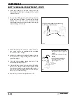
Loosen all rod end adjuster jam nuts see Ill. 1.
3.
Note orientation of tie rod end studs with stud up or
down.
Remove
both
rod
end
studs
from
transmission bell cranks.
4.
Be sure idle speed is adjusted properly.
NOTE: It is important to disconnect both rod ends from
the transmission bell cranks. If one linkage rod is incor-
rectly adjusted, it can affect the adjustment of the other
rod.
Correctly Tightened
Jam Nut
Incorrectly Tightened
Jam Nut
Parallel
Linkage rod will rotate
1/8 -1/4 turn if rod ends
are tightened properly.
Low Range
Gear Selector
Slides
Jam Nut
Jam
Nut
NOTE: Rod end orientation, rod ends are
both down.
Ill. 1
Summary of Contents for Sportsman 400
Page 6: ...SPORTSMAN 400 A01CH42AC GENERAL INFORMATION 1 4 MODEL COLOR IDENTIFICATION ...
Page 21: ...Newton Meter to Pound Foot and Pound Inch GENERAL INFORMATION 1 19 TORQUE CONVERSIONS ...
Page 22: ...Newton Meter to Pound Foot and Pound Inch GENERAL INFORMATION 1 20 TORQUE CONVERSIONS ...
Page 152: ...Forward FUEL SYSTEM CARBURETION 4 2 FUEL TANK ASSEMBLY ...
Page 366: ...ELECTRONIC SPEEDOMETER WIRING DIAGRAM ELECTRICAL 10 32 ...
Page 372: ...ELECTRICAL 10 38 NOTES ...
Page 379: ...ELECTRICAL 10 39 WIRING DIAGRAM 2001 SPORTSMAN 400 ...
Page 380: ...ELECTRICAL 10 40 WIRING DIAGRAM 2001 SPORTSMAN 500 EARLY ...
Page 381: ...ELECTRICAL 10 41 WIRING DIAGRAM 2001 SPORTSMAN 500 LATE ...


