TRANSMISSION
8.23
FRONT OUTPUT HOUSING (SNORKEL) INSTALLATION
9.
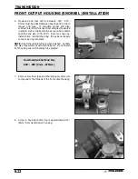
Install front output ring gear, washer, and retaining
bolt with a new lock plate. Hold shaft with strap
wrench and tighten retaining bolt. Clean threads of
bolt and shaft with Loctite
™
Primer N. Apply Loctite
™
242 or 243 (blue) to retaining bolt threads. Torque
bolt to specification and bend lock plate against
hexagonal portion of bolt.
10. Install pinion gear assembly and retaining plate. Use
Loctite
™
Primer N on threads and housing. Apply
Loctite
™
242 to bolts and torque to specification.
FRONT OUTPUT HOUSING (SNORKEL) BACKLASH ADJUSTMENT
11. Lubricate front housing O-ring thoroughly with
Polaris All Season grease. Continue to screw front
housing in, making sure O-ring enters housing
without damage. Be sure ring and pinion gear teeth
mesh properly.
12. Rotate front shaft while slowly turning housing
inward. As gear backlash is reduced to zero, the
shaft will begin to bind. At this point back off 1/4 turn.
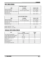
Ring Gear Retaining Bolt
17 - 20 ft. lbs. (24-27 Nm)
Apply Loctite
™
242 or 243 (Blue)
Pinion Gear Retainer Screws:
17 - 20 ft. lbs. (24-27 Nm)
Apply Loctite
™
242 or 243 (Blue)
Summary of Contents for Sportsman 400
Page 6: ...SPORTSMAN 400 A01CH42AC GENERAL INFORMATION 1 4 MODEL COLOR IDENTIFICATION ...
Page 21: ...Newton Meter to Pound Foot and Pound Inch GENERAL INFORMATION 1 19 TORQUE CONVERSIONS ...
Page 22: ...Newton Meter to Pound Foot and Pound Inch GENERAL INFORMATION 1 20 TORQUE CONVERSIONS ...
Page 152: ...Forward FUEL SYSTEM CARBURETION 4 2 FUEL TANK ASSEMBLY ...
Page 366: ...ELECTRONIC SPEEDOMETER WIRING DIAGRAM ELECTRICAL 10 32 ...
Page 372: ...ELECTRICAL 10 38 NOTES ...
Page 379: ...ELECTRICAL 10 39 WIRING DIAGRAM 2001 SPORTSMAN 400 ...
Page 380: ...ELECTRICAL 10 40 WIRING DIAGRAM 2001 SPORTSMAN 500 EARLY ...
Page 381: ...ELECTRICAL 10 41 WIRING DIAGRAM 2001 SPORTSMAN 500 LATE ...


