ELECTRICAL
10.24
STARTER ASSEMBLY
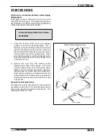
1.
Place armature in field magnet casing.
2.
Place shims on drive end of armature shaft with
phenolic washer outermost on shaft. Engage tabs
of stationary washer in drive end housing, holding it
in place with a light film of grease.
3.
Install case sealing O-Ring. Make sure O-Ring is
in good condition and not twisted on the case.
Lubricate needle bearing and oil seal with a light
film of grease, and install housing, aligning marks.
4.
Install O-Ring on other end of field magnet casing.
Make sure it is in good condition and not twisted on
the case.
5.
Align casing marks and install housing, pushing
back brushes while installing shaft in bushing.
6.
Reinstall starter motor housing bolts.
Make sure O-Rings are in good condition and seated in groove.
7.
Inspect permanent magnets in starter housing. Make sure they are not cracked or separated from housing.
CAUTION:
Use care when handling starter housing. Do not drop or strike the housing as magnet damage is possible. If
magnets are damaged, starter must be replaced.
Summary of Contents for Sportsman 400
Page 6: ...SPORTSMAN 400 A01CH42AC GENERAL INFORMATION 1 4 MODEL COLOR IDENTIFICATION ...
Page 21: ...Newton Meter to Pound Foot and Pound Inch GENERAL INFORMATION 1 19 TORQUE CONVERSIONS ...
Page 22: ...Newton Meter to Pound Foot and Pound Inch GENERAL INFORMATION 1 20 TORQUE CONVERSIONS ...
Page 152: ...Forward FUEL SYSTEM CARBURETION 4 2 FUEL TANK ASSEMBLY ...
Page 366: ...ELECTRONIC SPEEDOMETER WIRING DIAGRAM ELECTRICAL 10 32 ...
Page 372: ...ELECTRICAL 10 38 NOTES ...
Page 379: ...ELECTRICAL 10 39 WIRING DIAGRAM 2001 SPORTSMAN 400 ...
Page 380: ...ELECTRICAL 10 40 WIRING DIAGRAM 2001 SPORTSMAN 500 EARLY ...
Page 381: ...ELECTRICAL 10 41 WIRING DIAGRAM 2001 SPORTSMAN 500 LATE ...


