4
CHAPTER 4
FUEL SYSTEM/CARBURETION
Jetting Guidelines
4.1
. . . . . . . . . . . . . . . . . . . . . . . . . . . .
Main Jet Selection
4.1
. . . . . . . . . . . . . . . . . . . . . . . . . . . .
Fuel Tank Asm. Exploded View
4.2
. . . . . . . . . . . . . . . . .
Fuel Flow Diagram
4.3
. . . . . . . . . . . . . . . . . . . . . . . . . . . .
Main Jet / Pilot Jet Part Numbers
4.4
. . . . . . . . . . . . . . .
CV Carburetor System Function (4 Cycle)
4.5
. . . . . . .
CV Carburetor Vent System (4 Cycle)
4.5
. . . . . . . . . . .
CV Carburetor Operation
4.6-4.8
. . . . . . . . . . . . . . . . . . . . . .
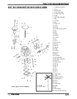
Exploded View, Mikuni BST 34 Carburetor
4.9
. . . . . . .
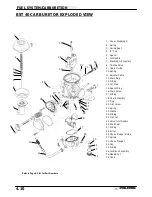
Exploded View, Mikuni BST 40 Carburetor
4.10
. . . . . . .
Disassembly Notes, CV Carburetor
4.11-4.12
. . . . . . . . . . . . .
Cleaning, CV Carburetor
4.12
. . . . . . . . . . . . . . . . . . . . . .
Inspection, CV Carburetor
4.13
. . . . . . . . . . . . . . . . . . . . .
Assembly, CV Carburetor
4.14
. . . . . . . . . . . . . . . . . . . . . .
Adjustment, CV Carburetor
4.15-4.16
. . . . . . . . . . . . . . . . . . . .
Fuel Pump Disassembly / Inspection / Assembly
4.17
.
Fuel Pump Exploded View
4.18
. . . . . . . . . . . . . . . . . . . . .
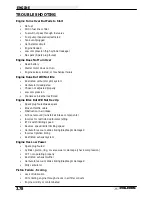
Troubleshooting
4.19-4.20
. . . . . . . . . . . . . . . . . . . . . . . . . . . . . .
Summary of Contents for Sportsman 400
Page 6: ...SPORTSMAN 400 A01CH42AC GENERAL INFORMATION 1 4 MODEL COLOR IDENTIFICATION ...
Page 21: ...Newton Meter to Pound Foot and Pound Inch GENERAL INFORMATION 1 19 TORQUE CONVERSIONS ...
Page 22: ...Newton Meter to Pound Foot and Pound Inch GENERAL INFORMATION 1 20 TORQUE CONVERSIONS ...
Page 152: ...Forward FUEL SYSTEM CARBURETION 4 2 FUEL TANK ASSEMBLY ...
Page 366: ...ELECTRONIC SPEEDOMETER WIRING DIAGRAM ELECTRICAL 10 32 ...
Page 372: ...ELECTRICAL 10 38 NOTES ...
Page 379: ...ELECTRICAL 10 39 WIRING DIAGRAM 2001 SPORTSMAN 400 ...
Page 380: ...ELECTRICAL 10 40 WIRING DIAGRAM 2001 SPORTSMAN 500 EARLY ...
Page 381: ...ELECTRICAL 10 41 WIRING DIAGRAM 2001 SPORTSMAN 500 LATE ...


