CLUTCH
6.44
BUSHING REPLACEMENT, EBS DRIVEN
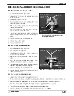
EBS Driven - Bushing Removal
1.
Install puller adapter (Item 10) onto puller.
2.
Insert EBS main adapter (Item D) onto puller. See Ill. 1.
3.
Install bushing removal tool (Item E) into center of
clutch sheave. See Ill. 2.
4.
Install sheave onto puller.
5.
Install left hand nut onto puller rod and tighten by
hand. Turn puller barrel for further tension if needed.
6.
Using a hand held propane torch, apply heat around
outside of bushing until tiny smoke tailings appear.
CAUTION: Clutch components will be hot! In order to
avoid serious burns, wear some type of insulated gloves
for the rest of the removal process.
7.
Turn clutch sheave counterclockwise until bushing is
removed and sheave comes free.
8.
Remove nut (C) (left hand thread) from puller rod and
set aside.
9.
Remove adapters from puller.
10. Remove bushing and removal tool from adapters.
Discard bushing.
EBS Driven - Bushing Installation
1.
Slide adapter (Item 10) onto puller.
2.
Apply Loctite
t
609 evenly to bushing bore inside
moveable sheave.
3.
Install sheave onto puller (belt surface up).
4.
Place new bushing on side B of installation tool (Item
A/B) and slide both over puller rod.
5.
Install nut (C) onto puller rod and hand tighten
against installation tool.
6.
Turn clutch sheave counterclockwise until bushing is
seated.
7.
Remove nut (C) (left hand thread) from puller rod and
set aside.
8.
Remove installation tool and clutch sheave from
puller.
Ill. 1
D
Ill. 2
Bushing
Removal Tool (E)
Nut (C)
Bushing
EBS Driven Clutch Bushing Installation
Puller Adapter (10)
Puller Tool (A/B)
Side “B” toward
sheave
Summary of Contents for Sportsman 400
Page 6: ...SPORTSMAN 400 A01CH42AC GENERAL INFORMATION 1 4 MODEL COLOR IDENTIFICATION ...
Page 21: ...Newton Meter to Pound Foot and Pound Inch GENERAL INFORMATION 1 19 TORQUE CONVERSIONS ...
Page 22: ...Newton Meter to Pound Foot and Pound Inch GENERAL INFORMATION 1 20 TORQUE CONVERSIONS ...
Page 152: ...Forward FUEL SYSTEM CARBURETION 4 2 FUEL TANK ASSEMBLY ...
Page 366: ...ELECTRONIC SPEEDOMETER WIRING DIAGRAM ELECTRICAL 10 32 ...
Page 372: ...ELECTRICAL 10 38 NOTES ...
Page 379: ...ELECTRICAL 10 39 WIRING DIAGRAM 2001 SPORTSMAN 400 ...
Page 380: ...ELECTRICAL 10 40 WIRING DIAGRAM 2001 SPORTSMAN 500 EARLY ...
Page 381: ...ELECTRICAL 10 41 WIRING DIAGRAM 2001 SPORTSMAN 500 LATE ...


