ELECTRICAL
10.23
ARMATURE TESTING
1.
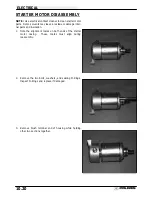
Remove armature from starter casing. Note order
of shims on drive end for reassembly.
2.
Inspect surface of commutator.
Replace if
excessively worn or damaged.
3.
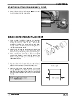
Using a digital multitester, measure the resistance
between each of the commutator segments. The
reading should be .3 ohms or less.
4.
Measure
the
resistance
between
each
commutator segment and the armature shaft. The
reading should be infinite (no continuity).
5.
Check commutator bars for discoloration. Bars
discolored in pairs indicate shorted coils, requiring
replacement of the starter motor.
6.
Place armature in a growler. Turn growler on and
position a hacksaw blade or feeler gauge
lengthwise 1/8
″
(.3 cm) above armature coil
laminates.
Rotate armature 360
°
.
If hacksaw
blade is drawn to armature on any pole, the
armature is shorted and must be replaced.
Summary of Contents for Sportsman 400
Page 6: ...SPORTSMAN 400 A01CH42AC GENERAL INFORMATION 1 4 MODEL COLOR IDENTIFICATION ...
Page 21: ...Newton Meter to Pound Foot and Pound Inch GENERAL INFORMATION 1 19 TORQUE CONVERSIONS ...
Page 22: ...Newton Meter to Pound Foot and Pound Inch GENERAL INFORMATION 1 20 TORQUE CONVERSIONS ...
Page 152: ...Forward FUEL SYSTEM CARBURETION 4 2 FUEL TANK ASSEMBLY ...
Page 366: ...ELECTRONIC SPEEDOMETER WIRING DIAGRAM ELECTRICAL 10 32 ...
Page 372: ...ELECTRICAL 10 38 NOTES ...
Page 379: ...ELECTRICAL 10 39 WIRING DIAGRAM 2001 SPORTSMAN 400 ...
Page 380: ...ELECTRICAL 10 40 WIRING DIAGRAM 2001 SPORTSMAN 500 EARLY ...
Page 381: ...ELECTRICAL 10 41 WIRING DIAGRAM 2001 SPORTSMAN 500 LATE ...


