MAINTENANCE
2.30
STEERING
The steering components should be checked periodically for loose fasteners, worn tie rod ends, and damage.
Also check to make sure all cotter pins are in place. If cotter pins are removed, they must not be re-used. Always
use new cotter pins.
Replace any worn or damaged steering components. Steering should move freely through entire range of travel
without binding. Check routing of all cables, hoses, and wiring to be sure the steering mechanism is not restricted
or limited. NOTE: Whenever steering components are replaced, check front end alignment. Use only genuine
Polaris parts.
WARNING
Due to the critical nature of the procedures outlined in this chapter, Polaris recommends steering component re-
pair and adjustment be performed by an authorized Polaris Dealer. Only a qualified technician should replace
worn or damaged steering parts. Use only genuine Polaris replacement parts.
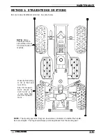
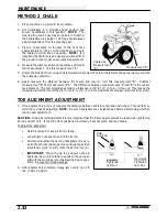
One of two methods can be used to measure toe alignment. The string method and the chalk method. If adjust-
ment is required, refer to following pages for procedure.
TIE ROD END / STEERING INSPECTION
S
To check for play in the tie rod end, grasp the steering
tie rod, pull in all directions feeling for movement.
S
Repeat inspection for inner tie rod end (on steering
post).
S
Replace any worn steering components.
Steering
should move freely through entire range of travel with-
out binding.
S
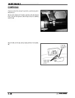
Elevate front end of machine so front wheels are off the
ground. Check for any looseness in front hub / wheel
assembly by grasping the tire firmly at top and bottom
first, and then at front and rear. Try to move the wheel
and hub by pushing inward and pulling outward.
S
If abnormal movement is detected, inspect the hub and
wheel assembly to determine the cause (loose wheel
nuts or loose front hub nut).
S
Refer to the Body/Steering or Final Drive chapter for
more information.
CAMBER AND CASTER
The camber and caster are non-adjustable.
Check for Loose Wheel or Hub
Summary of Contents for Sportsman 400
Page 6: ...SPORTSMAN 400 A01CH42AC GENERAL INFORMATION 1 4 MODEL COLOR IDENTIFICATION ...
Page 21: ...Newton Meter to Pound Foot and Pound Inch GENERAL INFORMATION 1 19 TORQUE CONVERSIONS ...
Page 22: ...Newton Meter to Pound Foot and Pound Inch GENERAL INFORMATION 1 20 TORQUE CONVERSIONS ...
Page 152: ...Forward FUEL SYSTEM CARBURETION 4 2 FUEL TANK ASSEMBLY ...
Page 366: ...ELECTRONIC SPEEDOMETER WIRING DIAGRAM ELECTRICAL 10 32 ...
Page 372: ...ELECTRICAL 10 38 NOTES ...
Page 379: ...ELECTRICAL 10 39 WIRING DIAGRAM 2001 SPORTSMAN 400 ...
Page 380: ...ELECTRICAL 10 40 WIRING DIAGRAM 2001 SPORTSMAN 500 EARLY ...
Page 381: ...ELECTRICAL 10 41 WIRING DIAGRAM 2001 SPORTSMAN 500 LATE ...


