CLUTCH
6.38
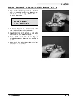
DRIVE CLUTCH INSPECTION, CONT.
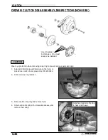
2.
Remove moveable sheave.
3.
Lift one-way clutch off shaft.
Replace as an
assembly if worn, damaged, or if problems were
noted on page 6.37.
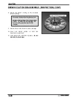
4.
Inspect surface of shaft for pitting, grooves, or
damage.
Measure the outside diameter and
compare to specifications. Replace the drive clutch
assembly if shaft is worn or damaged.
5.
Remove 2 1/2
″
PTFE washer from shaft. Visually
inspect the washer for damage.
Measure the
thickness and compare to specification. Replace if
worn or damaged.
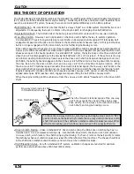
MOVEABLE SHEAVE BUSHING INSPECTION
1.
Inspect the Teflon
™
coating on the moveable sheave
bushing.
Shaft Diameter
Standard: 1.3745
″
- 1.375
″
Service Limit: 1.3730
″
PTFE Washer Thickness
Standard: .030
″
(.76mm)
Service Limit: .025
″
(.64mm)
Moveable Sheave Bushing Inspection:
Replace the cover bushing if more
brass than Teflon
™
is visible on the
bushing. Refer to bushing replacement
in this chapter.
Summary of Contents for Sportsman 400
Page 6: ...SPORTSMAN 400 A01CH42AC GENERAL INFORMATION 1 4 MODEL COLOR IDENTIFICATION ...
Page 21: ...Newton Meter to Pound Foot and Pound Inch GENERAL INFORMATION 1 19 TORQUE CONVERSIONS ...
Page 22: ...Newton Meter to Pound Foot and Pound Inch GENERAL INFORMATION 1 20 TORQUE CONVERSIONS ...
Page 152: ...Forward FUEL SYSTEM CARBURETION 4 2 FUEL TANK ASSEMBLY ...
Page 366: ...ELECTRONIC SPEEDOMETER WIRING DIAGRAM ELECTRICAL 10 32 ...
Page 372: ...ELECTRICAL 10 38 NOTES ...
Page 379: ...ELECTRICAL 10 39 WIRING DIAGRAM 2001 SPORTSMAN 400 ...
Page 380: ...ELECTRICAL 10 40 WIRING DIAGRAM 2001 SPORTSMAN 500 EARLY ...
Page 381: ...ELECTRICAL 10 41 WIRING DIAGRAM 2001 SPORTSMAN 500 LATE ...


