ENGINE
3.69
CAMSHAFT TIMING, CONT.
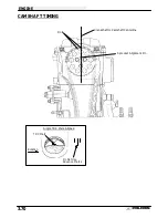
4.
Loop the cam chain on the cam sprocket with the
dots on the sprocket facing outward and the
alignment pin notch facing directly upward.
5.
Before positioning the sprocket on the camshaft,
check the position of the cam sprocket alignment
pin. When the cam is positioned properly, the cam
sprocket alignment pin (A) is directly in line with
the crankshaft/camshaft centerline (B).
6.
Install the sprocket on the camshaft. Apply Loctite
242 to the cam sprocket bolts and torque to
specifications.
7.
Verify TDC mark in timing inspection hole and
alignment pin is directly in line with crankshaft to
camshaft centerline.
Refer to Ill. on following
page.
8.
Apply 3 Bond 1215 (P/N 2871557) to the
camshaft end cap and install using a new O-Ring.
9.
Check all cam timing marks to verify proper cam
timing, and install the cam chain tensioner body
with a new gasket.
10. After tensioner installation, rotate engine at least
two revolutions and re-check marks/timing.
A
A
B
Cam Sprocket Bolt Torque:
6 ft. lbs. (.828 kg-m)
Single (TDC)
Mark Aligned
Summary of Contents for Sportsman 400
Page 6: ...SPORTSMAN 400 A01CH42AC GENERAL INFORMATION 1 4 MODEL COLOR IDENTIFICATION ...
Page 21: ...Newton Meter to Pound Foot and Pound Inch GENERAL INFORMATION 1 19 TORQUE CONVERSIONS ...
Page 22: ...Newton Meter to Pound Foot and Pound Inch GENERAL INFORMATION 1 20 TORQUE CONVERSIONS ...
Page 152: ...Forward FUEL SYSTEM CARBURETION 4 2 FUEL TANK ASSEMBLY ...
Page 366: ...ELECTRONIC SPEEDOMETER WIRING DIAGRAM ELECTRICAL 10 32 ...
Page 372: ...ELECTRICAL 10 38 NOTES ...
Page 379: ...ELECTRICAL 10 39 WIRING DIAGRAM 2001 SPORTSMAN 400 ...
Page 380: ...ELECTRICAL 10 40 WIRING DIAGRAM 2001 SPORTSMAN 500 EARLY ...
Page 381: ...ELECTRICAL 10 41 WIRING DIAGRAM 2001 SPORTSMAN 500 LATE ...


